background image

10

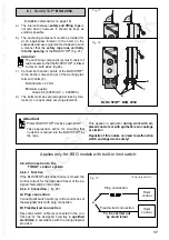
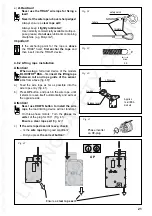
B.2 Setting the rated load

Attach  rated load  (e. g. 500 kg) and lift the
nominal load from ground.

Turn  lower regulator to the left as far as the
stop.

Press UP button  –  the hoist must stop immedi-
ately.

Following each stopping o

f the hoist during

this setting procedure, 

press the DOWN button

shortly

 so that the upward travel is again possi-

ble.

Step by step
– turn the lower regulator slightly to the right,
– then press UP button,
until lifting of the suspended nominal load is
possible.

Important note for TIRAK

®

  with  2 speeds

(pole changing motor):
The control system contains 2 load limiting
devices
, the setting  must be carried out for

both speeds.

3.8.4.2 Mechanical load limiting device

The load limiting device is installed in the rope drive
and switches off the UPWARD travel in the event of
overload.

A warning signal (lamp/buzzer) is triggered which
does not go off until the cause of the overload has
been removed.

Possible causes for the switching off:

overload of the suspended access equipment,
possibly as a result of unfavourable load distribu-
tion

or

the suspended access equipment being blocked
by an obstacle during upward travel

Action following switching off:

reduce load to such an extent that, or redistribute
it until there is no longer any overload,

or

move downwards until the suspended access
equipment is free from the obstacle which must
be removed before travel is continued.

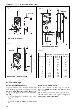
2

1

Fig. 8

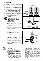
3.8.5 Manual operation

Details in chapter 5.5 on page 25.

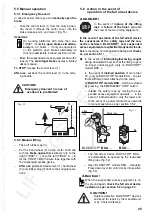
3.8.5.1 Emergency Descent

In case of power failure you can manually open
the brake
 with lever (1) (Fig. 8).

3.8.5.2 Manual lifting

With the brake opened the suspended ac-
cess equipment can be lifted with the hand
wheel (2) placed on the motor shaft. (Fig. 8).

3.8.6 Fall arrest devices

Suspended access equipment must be equipped with
a  fall arrest device which secures the load against
falling using a safety rope.

The two systems available from the manufacturer of
the TIRAK

®

 hoists are described below.

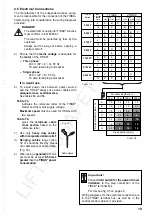
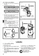
3.8.6.1  BLOCSTOP

®

  Model BSA

The fall arrest device model BLOCSTOP

®

  BSA is

opened by the loaded lifting rope (fig. 9) and secures
the suspended access equipment against:

a)

rupture of the lifting rope,

b)

failure of the hoist,

c)

interlocking/becoming caught during downward
travel with the result that the lifting rope is no
longer under tension,

d)

inclined position of more than the maximum ad-
missible 14

  (on suspended platforms with the

two hoists attached at the ends).

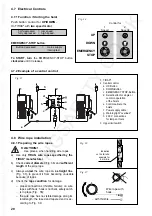
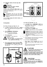
3.8.6.2  BLOCSTOP

®

  model BSO

The fall arrest device model BLOCSTOP

®

  BSO is

released manually (fig. 10).

The speed of the safety rope is constantly monitored
and the clamping mechanism closed automatically in
the event of a sudden occurrence of excessive speed.
As a result, the suspended access equipment is se-
cured against

a)

rupture of the lifting rope and

b)

failure of the hoist

By pressing the EMERGENCY STOP button the fall
arrest device can also be closed manually in an emer-
gency
. This offers the advantage that a defective
hoist can be replaced on the hanging man-riding de-
vice.

The  viewing window serves to enable to check the
operation of the centrifugal weights during service.

See section 5.6 on page 25 for action in the event
of operation of the fall arrest device
.

Summary of Contents for TIRAK T 1020 P

Page 1: ...00 P X 720 P X 820 P X 1030 P TIRAK series X 2050 P Original Operating Instructions This instruction manual must be available for the user at all times Additional copies may be obtained on request Ele...

Page 2: ...ers 18 4 6 Electric connections 19 4 7 Electric controls 4 7 1 Push button control UP DOWN 20 4 7 2 Examples for central control 20 4 8 Wire rope installation 4 8 1 Preparing the rope 20 4 8 2 Lifting...

Page 3: ...GREIFZUG GmbH or from another company of the TRACTEL Group shall receive the complete instructions for the corresponding installation Suspensions and Suspended platforms Original assembly and operati...

Page 4: ...ions to the devices supplied by itself or as a result of the use of non original parts Follow all instructions and safety regulations contained in this manual to avoid injuries a TIRAK hoists for man...

Page 5: ...d by the manufacturer This wire rope is mandatory for the safe and troublefree working with TIRAK hoists 3 2 Working principle A TIRAK hoist is installed on suspended access equipment with which it mo...

Page 6: ...endant control mounted on the terminal box d with pendant control with connector 5 Where appliable connector to the central control box 6 Always connector to the upper limit switch at the TIRAK termin...

Page 7: ...2 14 110 660 400 350 3 6 Technical Data 3 6 1 TIRAK Hoists Table 2 1 Hoist to 9 m min Driving group 1Bm Hoists over 9 m min Driving group 1Cm 2 If the capacity is not sufficient in direct pull multipl...

Page 8: ...7 6 5 3 4 1 2b 7 6 Working cage 5 4 3 1 2b 7 6 Working seat Schematical Drawing 1 TIRAK 2a BLOCSTOP BSA Fall arrest device 2b BLOCSTOP BSO Fall arrest device 3 Lifting rope 4 Safety rope 5 Tensioning...

Page 9: ...to the right as far as the stop A 2 Start bridging Turn lower regulator to the right as far as the stop 3 8 4 Load limiting device 3 8 4 1 Electronic load limiting device The load limiting device is s...

Page 10: ...power failure you can manually open the brake with lever 1 Fig 8 3 8 5 2 Manual lifting With the brake opened the suspended ac cess equipment can be lifted with the hand wheel 2 placed on the motor s...

Page 11: ...set by the manufacturer b The electronic load limiting device only de tects an overload during lifting upward travel Therefore special care must be given to the dis tribution of the loads c The BLOCST...

Page 12: ...26 q 13 13 Table 4 Anchoring devices Series X 300 400 500 720 820 P and X 1030 P when screwing the housing to the points A M10x screws at least grade 8 8 with self locking nuts series X 300 400500 720...

Page 13: ...eries T 1020 P h g c b a i C D i Fig 15 h g c b a d i f e A B Fig 13 Fig 12 k p l o n m q b c a d A Series X 300 400 P Fig 14 Adapter optional for Series X 300 400 500 720 820 1030 P Series X 500 720...

Page 14: ...t least at two of the four anchoring points A1 to A4 allowed A1 A 2 A2 A 3 A3 A 4 Attention NOT allowed anchoring only at points A1 A 3 or A1 A 4 or A2 A 4 Attention It must be ensured by means of the...

Page 15: ...RAK Hoists Attention When using an anchor bolt with safety pin Check the correct position of the safety pin according to Fig 20 Dimensions in mm for BLOCSTOP BSA Dim BSA 15 301 BSA 20 303 330 BSA 35 3...

Page 16: ...A BLOCSTOP BSA Anchor the BLOCSTOP Device to both anchor points A in such a manner fig 24 that there is 10 cm interval S BSA 15 20 or 20 cm interval S BSA 35 305 between safety rope and lifting rope...

Page 17: ...ly for BSO models with built in limit switch 4 4 4 Connection to the TIRAK control system 4 4 4 1 Function If the BLOCSTOP fall arrest device is closed the control current for the downward travel of t...

Page 18: ...rope winders e g motor or spring rope drums When planning we recommend consulting the manu facturer of the TIRAK hoists regarding design and arrangement of the rope winders Fig 32 Dimensions in mm for...

Page 19: ...on the reference letter c Use only heavy duty cables with incorporated strain relief d Hanging cables longer than 30 m should be fixed by means of a cable sleeve or cable clamp Fig 33 e When using a...

Page 20: ...wire rope in a straight line Fig 37 to prevent it from becoming unusable because of loops d Check the rope condition for damage proper connections thimble ferrule on wire ropes with hook hook is not...

Page 21: ...80 Fig 41 Ensure a clear rope exit fig 42 c If the wire rope does not reeve check Is the wire rope tip in good condition Did you press the correct button Fig 40 Fig 42 UP Fig 41 Phase inverter on CE p...

Page 22: ...m above the ground fig 45 9 5 kg for BSA 15 301 20 303 20 330 and BSO 500 1020 1030 2 x 9 5 kg for BSA 35 305 and BSO 2050 Fig 43 BLOCSTOP BSA Fig 44 Fig 45 Lifting rope A Safety rope Counterweight ST...

Page 23: ...safety rope can however still be pulled upwards replace BLOCSTOP and send to the supplier for checking Re open the fall arrest device by pressing down the lever and sharply pull the safety rope upwar...

Page 24: ...is securely held at any position by the primary brake d In the event of inclined position Move lower TIRAK upwards with the UP button until the platform again hangs horizon tally With central control...

Page 25: ...rope or failure of the hoist evacuate the crew of the man riding equipment In the event of operation of the fall arrest device the suspension of the safety rope and the con nection between BLOCSTOP a...

Page 26: ...On 3 phase motors two phases c Turn phase inverter of changed in the supply the the central control built in phase control relay plug by 180 blocks the hoist control d Defect connection between d Chec...

Page 27: ...free B5 One phase is missing Check fuses and leads B6 Error in the UP control circuit Check connections wiring contactors of the central control and replace if necessary or the TIRAK hoist B7 lack of...

Page 28: ...gging speed too low f Replace BLOCSTOP and send with BLOCSTOP BSA for checking DANGER Defective BLOCSTOP fall arrest devices endanger the operational safety of the installation They must be replaced a...

Page 29: ...ote Lubricator nipple Fig 53 Deadline Details Performer on page Each working day Anchoring parts Safety requirements on 23 Supervisor TIRAK hoists suspended access 23 BLOCSTOP equipment 23 fall arrest...

Page 30: ...and without visible damage Attention If during operation damage appears STOP operating if necessary cordon off the danger zone and have the damage removed by a qualified person b Nameplates and labels...

Page 31: ...ing a fall arrest a qualified person must check the operational safety of the BLOCSTOP fall arrest device including an chor points as well as the safety rope and the rope anchoring It is the responsib...

Page 32: ...trol box of the motor 9 4 BLOCSTOP fall arrest device As well as the spare part number and description please always quote BLOCSTOP model wire rope diameter and serial number 9 5 Nameplates and labels...

Page 33: ...control lever has to return to its CLOSED position 2 During operation the centrifugal weights must rotate Check regularly through the window If during the above checks the BLOCSTOP malfunctions repla...

Page 34: ...position horizontal inclined vertical Also moves with load on the rope T 1020 series pulls in both directions compared to a crane or drum winch of the same carrying capacity and range Saves space weig...

Page 35: ...ative to scaffolding Suspended platforms working cage seat These new mobile platforms and seats with unlimited travel height for assembly inspection and repairs offer you the comfort of a lift combine...

Page 36: ...Safety first is the overriding objective The appropriate equipment must be put together depending on the location and work to be performed The product range of our safety program offers the following...

Reviews: