11
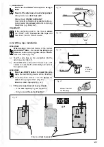
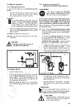
3.8.7 Upper limit switch
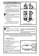
For each TIRAK
®
hoist a limit switch must be assem-
bled at the upper end of the support frame/support
stirrup of the suspended access equipment which
stops operation of upward travel when pressed
(fig. 11).
Fig. 11
lifting
rope
Rope anchor
Upper limit
switch
Limit switch
buffer plate
3.9
Residual risks
CAUTION!
The following risks are not constructively
covered for the TIRAK
®
hoist and the
BLOCSTOP
®
fall arrest devices:
a)
The load limiting device is set to the maximum
rated capacity of the respective hoist; the manu-
facturer of the suspended access equipment must
check whether the admissible overall weight of
his installation (own working load) cor-
responds to this value.
Should a lower value be necessary,
– have electronic load limiting device set by
qualified personnel;
(see section 3.8.4 load limiting device)
– have mechanical load limiting device set by
the manufacturer.
b)
The electronic load limiting device only de-
tects an overload during lifting/upward travel.
Therefore special care must be given to the dis-
tribution of the loads.
c)
The BLOCSTOP
®
fall arrest devices only fulfil
their safety function if the safety rope between
rope anchor and BLOCSTOP
®
is tensioned (no
slack rope!).
Therefore on safety ropes hanging down loosely,
a counterweight must always be secured 20 cm
above the ground (see 4.8.3).
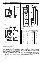
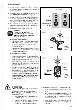
a
loaded
lifting rope
safety rope
slack
lifting rope
Cases
a) to c)
Fig. 9
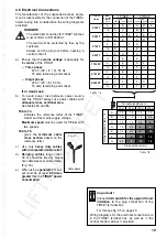
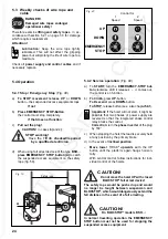
Platform in
excessively
inclined
position
Case d)
Fig. 10
STOP
AUF
EMERGENCY
STOP
Closed
OPEN
Window
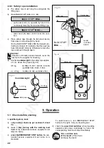
A buffer plate must be assembled underneath the
rope anchor on the lifting rope which triggers the limit
switch. If possible the interval (a) to the rope anchor
should be 1.5 metres or more.
With projecting components attach the buffer plate
sufficiently well below the rope anchor that the sus-
pended access equipment stops in good time.
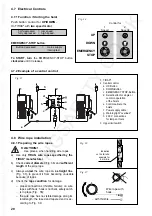
Attention! If the limit switch has been triggered,
press the DOWN button until the limit switch is
again switched free.


