14
90
wire rope
under load
slack
wire rope
Fig. 17
B
Adapter
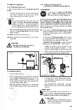
4.3.2
Anchoring the TIRAK
®
hoist
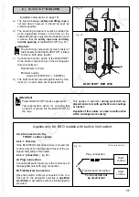
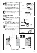
Attention:
ALWAYS anchor the TIRAK
®
hoist in such
way that the wire rope enters the hoist per-
pendicularly, when under load (Fig. 17 to 19).
A) TIRAK
®
-Series
X 300 / 400 / 7500 / 720 / 820 / 1030 P
(Fig. 17)
– Anchor TIRAK
®
hoist with bolt or
S
hackle at
point (B), or
– anchor the TIRAK
®
hoist at least at two of
the four anchoring points (A);
allowed:
A
1
<–>A
2
,
A
2
<–>A
3
,
A
3
<–>A
4
Attention!
NOT allowed: anchoring only
at points
A
1
<–>A
3
or A
1
<–>A
4
or A
2
<–>A
4
.
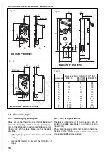
B) TIRAK
®
-Series X 2050 P
(Fig. 18)
– Anchor TIRAK
®
hoist with bolt or
S
hackle at
point (B).
Attention:
Support TIRAK
®
hoist with additional adapters
in the direction of pull.
– Or anchor the TIRAK
®
hoist at least at two of
the four anchoring points (A
1
to A
4
);
allowed:
A
1
<–>A
2
, A
2
<–>A
3
,
A
3
<–>A
4
,
Attention!
NOT allowed: anchoring only
at points A
1
<–>A
3
or A
1
<–>A
4
or A
2
<–>A
4
.
Attention:
It must be ensured by means of the mounting
(C) that the force is distributed evenly over
both anchoring points.
Important:
When planning the anchoring we recommend
consultation with the manufacturer.
Fig. 18
Series X 300/400/500/720/820/1030 P
Series X 2050 P
A
1
A
2
A
4
A
3
Fig. 19
90
D
Wire rope
under load
Slack wire
rope
C
Series T 1020 P
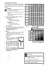
C) TIRAK
®
-Series T 1020 P
(Fig. 19)
– Anchor the TIRAK
®
hoist at the two points
(C and D).
In this respect the anchoring point at (C) must
be sufficient for the full carrying capacity of
the hoist whilst the anchoring at (D) merely
serves to stabilise the hoist.
90
wire rope under load
slack
wire rope
B
A
1
C
Mounting
for lateral
anchoring
A
2
A
4
A
3
flat steel 60 x 12,
165 long
Square tube
120 x 4.5, DIN 59410


