16
B) BLOCSTOP
®
BSO 500 und
BSO 1020/1030
(Installation dimensions on page 18)
a)
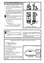
The interval between safety and lifting rope is
not laid down; however it should be kept as small
as possible.
b)
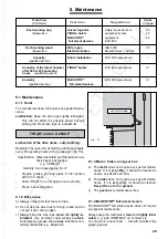
Anchor the BLOCSTOP
®
device to the anchor-
ing point (A) in such a manner that the safety
rope runs vertically into the opening of the
BLOCSTOP
®
(fig. 26). If necessary guide the
safety rope over deflection pulleys.
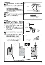
Attention: Do not fully tighten screw; the
BLOCSTOP
®
models BSO 500 and BSO
1020/1030 must be capable of swivelling
around the anchoring point (A).
STOP
AUF
STOP
AUF
Fig. 26
A
90
90
BSO 1020/1030
BSO 500
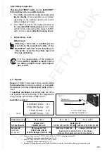
Fig. 25
Swivel
anchoring
not permitted!
4.4.3 Anchoring the fall arrest device
A) BLOCSTOP
®
BSA …
–
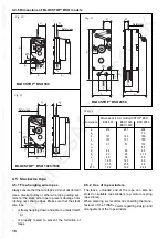
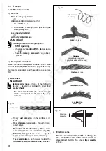
Anchor the BLOCSTOP
®
Device to both anchor
points (A) in such a manner (fig. 24) that there is
10 cm interval (S) BSA 15/20… or
20 cm interval (S) BSA 35-305
between safety rope and lifting rope
(fig. 21 to 23).
–
The component to which the BLOCSSTOP
®
type
BSA... is anchored must be connected rigidly to
the suspended access equipment.
Otherwise the BLOCSTOP
®
cannot function as
an inclination limiting device (fig. 25).
Attention!
Protect BLOCSTOP
®
devices against dirt!
(Details see page 17).
Anchoring devices
BSA 15-301 / 20-303 / 20-330:
M12x… screws, at least grade
8.8 with self-locking nuts;
BSA 35-305:
M22x… screws, at least grade
8.8 with self-locking nuts;
or bolts or similar with at least the
same strength.
Fig. 24
A
Anchoring devices
M12x… screws, at least grade 8.8
with self-locking nuts;
or bolts or similar with at least the
same strength.
Applies
to all BSA
models not
illustrated.


