22
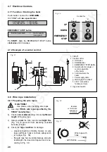
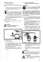
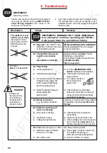
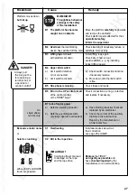
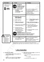
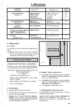
4.8.3 Safety rope installation
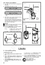
a) The safety rope must hang free alongside the
lifting rope.
b)
Open BLOCSTOP
®
(Abb. 43 + 44):
A)
BLOCSTOP
®
BSA …
– push sensor arm (A) upwards by hand if it is
not already raised by the tensioned lifting rope.
B)
BLOCSTOP
®
BSO …
– press lever (B) down until it locks into posi-
tion.
c)
Place safety rope through the fall arrest device
from above and pull taught by hand.
On the BLOCSTOP
®
BSO 2050 the forward pro-
truding control pin (C) indicates that the rope has
been introduced correctly. Otherwise remove the
rope and push through again.
Attention!
Should it still not protrude forward, send the
device to the supplier for checking.
d)
Anchor counterweight to the safety rope approx.
20 cm above the ground (fig. 45):
9.5 kg
for BSA 15-301 / 20-303 / 20-330
and BSO 500 / 1020 / 1030;
2 x 9.5 kg
for BSA 35-305 and BSO 2050
Fig. 43
BLOCSTOP
®
BSA …
Fig. 44
Fig. 45
Lifting rope
A
Safety rope
Counterweight
STOP
AUF
Safety rope
B
1 x 9.5 kg
2 x 9.5 kg
Safety rope
5. Operation
5.1
Checks before starting
A qualified person must
a)
carry out the checks as per sections 5.2 and
5.3,
b)
make a trial journey with the working load
limit of the suspended access equipment and
when so doing
c)
press the EMERGENCY STOP button, the sus-
pended access equipment must come to a
standstill.
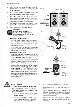
To switch back on, turn EMERGENCY STOP
button to the right. Carry on travelling and
d)
check the upper limit switches: when travelling
upwards press down individually by hand, the
corresponding hoist must stop immediately.
Make a written note
of the result of this check
and keep the report.
STOP
AUF
B
C
Applies
to all BSA
models.


