4
Before you begin, consider the following
installation guidelines:
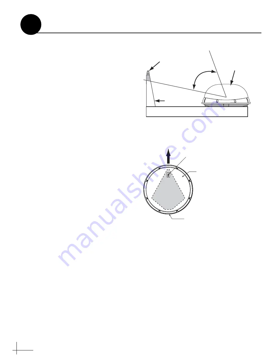
• Minimize blockage. The antenna requires a
15° to 75° look angle to receive satellite
• Mount the antenna no higher than half the
length of the vessel above the waterline.
• Choose a mounting surface that is flat, strong
enough to support the antenna’s weight
(34 lbs, 15 kg), and rigid enough to withstand
vibration without flexing.
• The antenna must be kept out of line with
nearby radars to avoid damage.
• Select an antenna mounting location on the
centerline of the vessel with the antenna’s
cable connectors facing the rear of the vessel
• Identify a safe location for the 3/4" (19 mm)
cable access hole in the deck. The cable access
hole should be located at least 6" (15 cm)
away from the antenna’s baseplate
connectors (see Figure 4). Make sure you will
not drill into any existing wires or aesthetic
structures inside the vessel.
• Choose a dry, flat location for the switchplate
that will be easily accessible to the user. Take
into account the lengths of the cables, as well
as accessibility to the equipment after
installation.
NOTE:
If you need a longer power/data cable, KVH
offers 45-foot (KVH part #32-0730-45) and 60-foot
(KVH part #32-0730-60) cables.
•
Circular only:
Identify a location for the grounding block
within 27 feet of the antenna, within 5 feet of
the receiver(s), and within 25 feet of a suitable
chassis ground location.
Figure 3: Blockage from Obstruction
Blocked!
Antenn
a
M
as
t
15-75
˚
Ve
ss
el Pl
a
tform
Figure 4: Antenna Orientation
Radome
Bow
Mounting
Plate
Baseplate
Connectors
Forward
Arrow
Plan the Installation
2


