TracVision R5SL/R4SL
3
RF PCB Replacement Instructions
c.
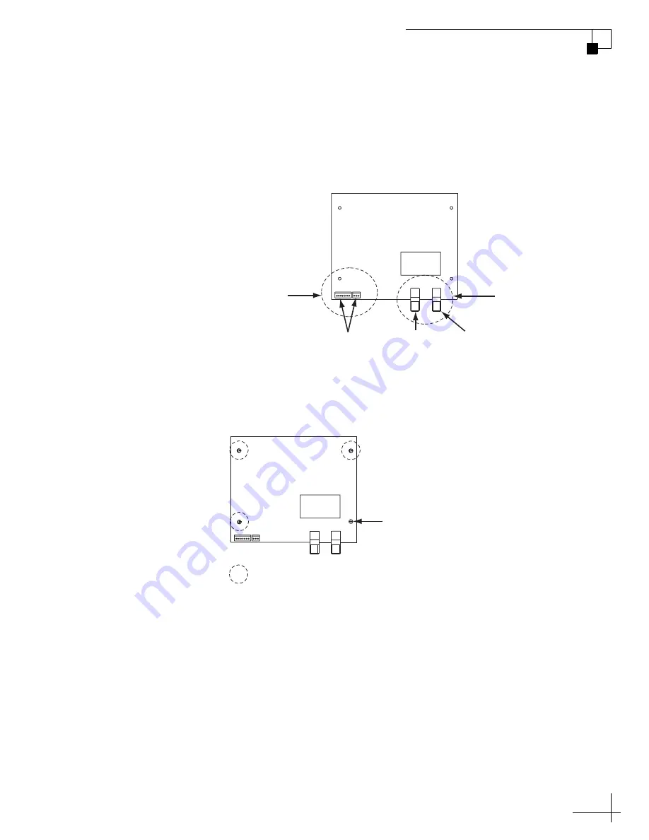
Disconnect the two Molex connectors from the RF PCB.
Using a 7/16" open-end wrench, disconnect the two RF
connectors from the RF PCB. Tag the RF cables first to
ensure they are returned to the correct connectors on
the new RF PCB.
Figure 3 RF PCB Connectors
d.
Using a #1 Phillips screwdriver, remove the screw
securing the RF PCB to the rotating plate.
Figure 4 RF PCB Screw and Standoffs
RF PCB
RF
Connectors
Molex
Connectors
From
Main PCB
To
Receiver
To
LNB
J6
J4
T
O
IRD
FR
OM LNB
RF PCB
J6
J4
T
O
IRD
FR
OM LNB
Screw
= Standoffs (x 3)


