background image

5

INSTALLATION DETAILS 

1)

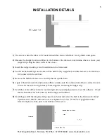
The alcove where the tub is to be located should be clean of all debris, level, plumb, and square. 

2)

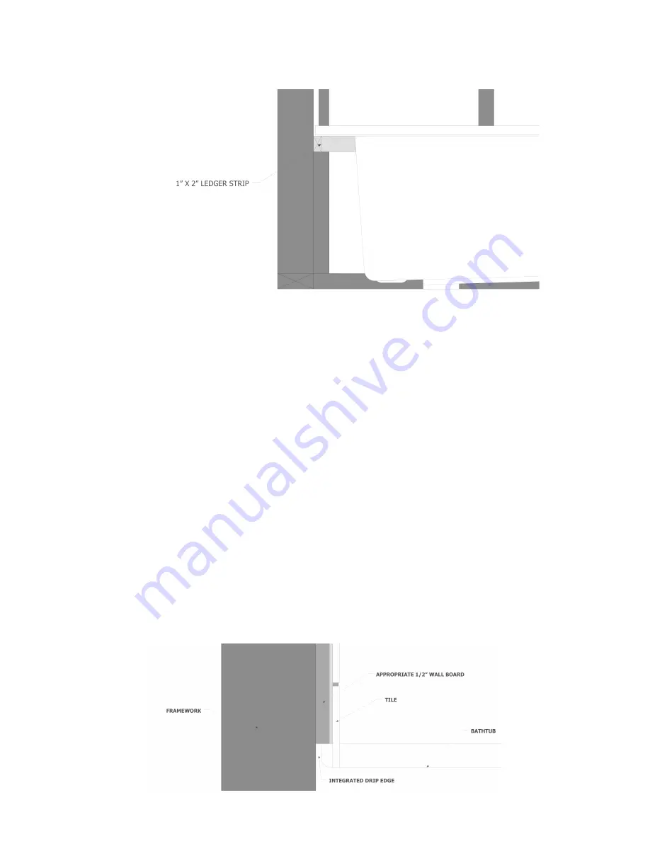
Measure the height from the subfloor to the bottom of the tub deck to determine where to locate your 

ledger strip along the three walls of the alcove. 

3)

Install the ledger insuring a level installation to the framework. 

4)

Test fit the bath making sure the deck of the bath is fully supported, and that the base to the bath is in 

full contact with the subfloor. 

5)

Remove the bath from the alcove and flip the tub upside down. 

6)

Apply a liberal amount of construction adhesive (make sure the construction adhesive states it is safe 

for use on foam) to the high density foam supports, and along the ledger stip. 

7)

Carefully set the tub back into its location right side up and apply pressure to set the adhesive.  Check 

the deck and base for full contact with the ledger and subfloor. 

8)

Carefully pre drill the integrated drip edge at each stud and screw the bath to the framework.  Hand 

tighten screws ,and be cautious to not over tighten the screws.  If the tub is gapped from the 
framework place a shim prior to installation of the screw. 

7612 Drag Strip Road – Fairview, TN 37062 – 615/799-8300 – www.tradewindinc.com 

Summary of Contents for ST3060LH

Page 1: ...y occur during shipping or in the ac tual installation It is required that the unit be field tested prior to final installation Failure to do so may result in voiding the manufacturer s warranty Under no circumstances will the manufacturer be liable for any damage due to leaks by the unit HOW TO WATER TEST Fill the unit with water to a level one inch above the jets and visually inspect all fitting...

Page 2: ...nnect the unit and have the problem corrected by a qualified electrician 6 Never operate this unit without the guard strainer over the suction fitting 7 FOR PERMANENTLY CONNECTED UNITS A green colored terminal or a wire connector marked G GR Ground or Grounding is provided within the terminal compartment To reduce the risk of electric shock connect this terminal or connector to the grounding termi...

Page 3: ...ly with all applicable local codes 6 Location of the TIMER or SWITCH for the unit must be in compliance with all local codes to eliminate the possibility of electric shock THE UNITS POWER SOURCE MUST BE ON A GFCI GROUND FAULT CIRCUIT INTERRUPTOR 7 ALL BUILDING MATERIALS AND WIRING SHOULD BE ROUTED AWAY FROM THE PUMP BLOWER OR ANY OTHER HEAT PRODUCING COMPONENTS 8 UNDER NO CIRCUMSTANCES should the ...

Page 4: ...th the subfloor The supporting base made on the tub is designed to carry the total load of the tub 4 An access panel MUST be left for service and inspection of the pump blower and any electrical con nections This access panel needs to be at least 16 x 20 5 This unit MUST be water tested for leaks before the unit is completely enclosed 6 All rough in dimensions are for reference only and actual mea...

Page 5: ...lcove and flip the tub upside down 6 Apply a liberal amount of construction adhesive make sure the construction adhesive states it is safe for use on foam to the high density foam supports and along the ledger stip 7 Carefully set the tub back into its location right side up and apply pressure to set the adhesive Check the deck and base for full contact with the ledger and subfloor 8 Carefully pre...

Page 6: ...6 7612 Drag Strip Road Fairview TN 37062 615 799 8300 www tradewindinc com ...

Page 7: ...um press a third time for low speed and to turn the blower off press the button a fourth time 2 The unit will run for twenty minutes and turn itself off If you desire to restart the unit for another twenty minute cycle repeat step one 3 When the unit is turned off for the final time the purge cycle is started After twenty minutes the unit will automatically turn itself on for one minute The purpos...

Page 8: ...il the de sired volume is reached The button will cycle between the increase mode and decrease mode every time the button is released and then pressed again 3 The system has two pulse cycles that are controlled by the right button Press this button once for an increas ing decreasing cycle and twice for an on off cycle 4 To deactivate the Thermal Air press the ON OFF button PURGE CYCLE When the The...

Page 9: ...aners Alcohol or mineral spirits may be used on difficult cleaning areas Scratches may be removed by sanding and buffing the surface However you should first consult a professional or contact the manufacturer before performing this task A mild polishing agent such as Jewelers Rouge or very mild abrasive toothpaste can be used on slight surface scratches Always polish with a soft cotton cloth DuPon...

Page 10: ...iginal installation and or installed by methods other than those shown on the installation sheets provided This warranty shall not apply and we shall have no liability for damages resulting from abuse or misuse of the unit or accidental damage incurred during installation The unit is carefully inspected before shipment and any chips cracks or blisters are to be considered shipping or handling dama...

Reviews: