AIR SUPPLY AND CONNECTIONS
The compressed air power source shall be pressure-regulated. The regulated
pressure must not exceed the maximum air pressure marked on the tool. If a
regulator fails, the pressure delivered to the tool must not exceed 1.5 times the
maximum air pressure, or 180 PSI, whichever is greater.
Pressure regulators shall be used to limit the air pressure supplied to the tool.
Regulators shall be set at an operating pressure which is lower than or equal to the
tool manufacturer’s specified maximum air pressure.
Air supply hoses shall have a minimum working pressure rating equal to or greater
than the pressure from the power source if a regulator fails, or 120 PSI, whichever is
greater.
Tools shall be fitted with a fitting or hose coupling on or near the tool in such a manner
that all compressed air in the tool is discharged at the time the fitting or hose coupling
is disconnected.
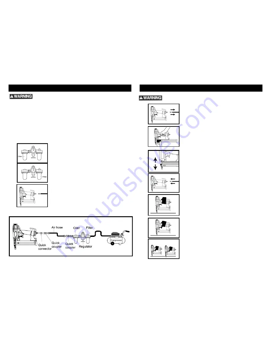
Many air tool users find it convenient to use an
oilier to help provide oil circulation throughout
the tool and to increase the efficiency and useful
life of the tool. Check oil level in the oilier daily.
Many air tool users find it convenient to use a
filter to remove liquids and impurities which can
rust or wear internal parts of the tool. A filter can
also increase the efficiency and usefulness
of the tool. The filter must be checked on a daily
basis, and if necessary, drained.
For better performance, install a 3/8” quick
connector (1/4” NPT threads) with an inside
diameter of .315” on your tool and a 3/8” quick
coupler on the air hose.
The following illustration shows the correct mode of connection to the air supply
system which will increase the efficiency and useful life of the tool.
TESTING THE SAFETY TRIP MECHANISM
Never point any operational fastener driving tool at yourself or at any other
person.
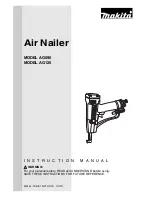
Disconnect the air supply from the tool.
Insert a stick of fasteners into the magazine. See section
on “Loading Fasteners Into The Nailer”.
Press down on workpiece and release the contact safety
trip mechanism. Verify there is no binding, sticking or
jamming of this mechanism.
Reconnect the air supply to the tool.
Depress the contact safety trip mechanism against the
workpiece without pulling the trigger. The tool must not
cycle. Never use the tool if a cycle occurs.
Hold the tool clear of the workpiece. The contact safety trip
mechanism should return to its original down position. Pull
the trigger. The tool must not cycle. Do not use the tool if a
cycle occurs.
To complete the testing procedures, depress the contact
safety mechanism against the workpiece and pull the
trigger, the tool must cycle.
4
5
Summary of Contents for Magnesium 8510
Page 8: ...NOTES NOTES 14 15...


