background image


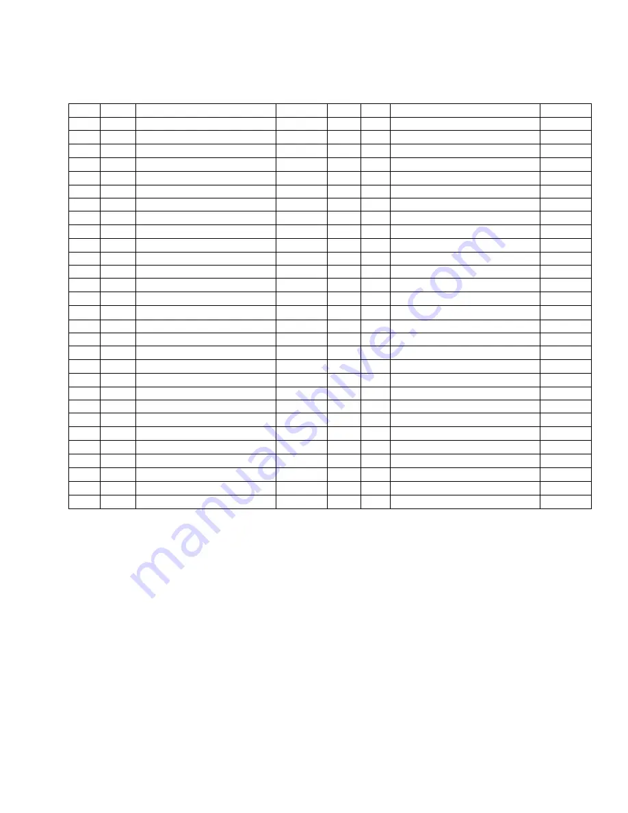
BBQ07E PARTS LIST 


Item 

Qty 

Description 

P/N 

Item 

Qty 

Description 

P/N 

Grill Frame Assembly 

SUB052 

102 

3” Caster W/O Brake 

HDW301 

 Washer .300 x .600 Zinc 

HDW271 

104 

Wheel Leg 

FAB019 

20 

Hopper Burner Assembly 

SUB110 

106 

6” Vipor Wheel 

HDW300 

22 

Burner Box Assembly 

SUB002 

107 

Shoulder  Bolt 3/8-16 Thread 

HDW131 

30 

Auger Assembly 070, 07E 

SUB005 

108 

Washer 5/16 Flat Zinc 

HDW120 

35 

Auger Tube Bushing 

BRN109 

109 

Nut 3/8-16 Acorn 

HDW132 

36 

Auger Drive Motor 

BRN100 

112 

Grease Bucket 

HDW152 

37 

Screw 6-32 x .750 Socket Hd 

HDW116 

113 

Flue Pipe Assembly 

FAB309 

38 

Nut 6-32 Nylock Zinc 

HDW112 

119 

Chimney Cap Assembly Bronze 

SUB150 

39 

Screw 8-32 x .375 S-tap 

HDW114 

126 

Flue Pipe Gasket 

INS145 

40 

Firepot Assembly 

FAB310 

Bolt 1/4-20 x .47 Hex Head 

HDW088 

46 

Hot Rod (Ignitor) 

BAC199 

Washer 1/4 Flat Zinc 

HDW130 

47 

Screw #8 x .5 Hex S-Tap 

HDW119 

Bolt 5/16-18 Socket Black 

HDW005 

48 

3/8 x 3/16 Thick Gasket  

BRN900 

Nut 5/16-18 Hex Black 

HDW006 

49 

Draft Inducer Fan Assy 

FAN209 

Washer 5/16 Lock Black 

HDW008 

50 

Power Cord 8’ Nema 120v 

ELE203 

16 

Washer 5/16 Flat Black 

HDW007 

51 

Strain Relief 

ELE210 

Bolt 1/4-20 x .310 Hex Zinc 

HDW088 

61 

Hopper Lid Assembly 

SUB167 

140 

Heat Baffle 

BCA012 

66 

Nut 8-32 K-Lock Zinc 

HDW108 

141 

Drain Pan 

BCA070 

67 

Screw 8-32 x .25 PPHD Zinc 

HDW079 

143 

12” Chrome Handle 

HDW227 

68 

Screw 6-32 x .375 S-Tap 

HDW115 

147 

Porcelain Grill 

HDW195 

69 

DIGITAL CONTROL W/SDC 

BAC283 

152 

Burner Gasket 

INS144 

70 

Screw 6-32 x .375 S-Tap 

HDW115 

153 

Hopper Top Level Assembly 

SUB177 

71 

7” RTD Sensor 

BAC194 

Nut 1/4-20 Hex 

Hdw123 

80 

Door Assembly Bronze 07E 

SUB178 


91 

Screw 8-32 x .5 PH Truss Zinc 

HDW117 


99 

Caster Leg 07E, 075 

FAB020 


101 

Square Leg Insert 

HDW303 


Summary of Contents for BBQ075.01

Page 1: ...ntire manual before assembly installation of your Traeger Pellet Grill Failure to follow these instructions could result in property damage bodily injury or even death Contact your local building or fire official about restrictions and installation inspection requirements in your area SAVE THESE INSTRUCTIONS ...

Page 2: ...UM distance of 12 from the Grill to combustibles WARNING When operating this Grill under overhead combustibles a MINIMUM of 40 inches is required WARNING Assemble and operate this Grill ONLY per the instructions in this Owner s Manual WARNING This Grill is intended for OUTDOOR USE ONLY WARNING Never use heating fuel pellets in the Grill due to potential hazardous contaminants and additives that ma...

Page 3: ...at Baffle 140 1 Flue Pipe 113 1 Chimney Cap Assembly 119 1 Chrome Door Handle 143 1 Grease Bucket 112 1 Hardware Kit NA You will need to complete the assembly which includes 1 Mounting the Caster Leg Assemblies 99 and the Wheel Leg Assemblies 104 to the Grill 2 Attaching the Chrome Door Handle 143 to the Door 80 3 Attaching the Flue Pipe 113 to the Grill Frame Assembly 2 4 Mounting the Chimney Cap...

Page 4: ...s 99 on the left end of the Grill and the Wheel Leg Assemblies 104 on the right end of the Grill as shown in the upper diagram below The Nuts C on the Wheel Leg Assemblies 104 should go toward the center of the Grill You may need to rotate the Grill toward the back to accommodate the Leg Assemblies 99 104 on the rear of the Grill Leave the Nuts loose during this step 3 Set the Grill upright to lev...

Page 5: ...rs 132 on two of the 1 2 long Hex Head Bolts 129 and insert the Bolts through the holes in the Flue Pipe 113 and the Flue Pipe Gasket 126 Align the Bolts with the corresponding holes in the Grill Place a Zinc Flat Washer 132 on each Bolt inside the Grill and secure with Zinc Hex Nuts 154 using the Wrench supplied 2 Screw the Chimney Cap Assembly 119 into the Bracket in the top of the Flue Pipe Han...

Page 6: ...ting to transport POSITIONING THE HEAT BAFFLE 1 Position The Heat Baffle 140 directly over the Firepot on the locating brackets found on the inside walls of the Grill The notched legs of the Heat Baffle 140 should be facing downward to fit onto the locating brackets POSITIONING THE GREASE DRAIN PAN 1 Position the Grease Drain Pan 141 so that the Short Lip end hooks over the Grease Drain Pan Suppor...

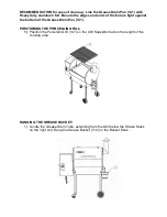
Page 7: ...t against the bottom of the Grease Drain Pan 141 POSITIONING THE PORCELAIN GRILL 1 Position the Porcelain Grill 147 on the Grill Supports that run the length of the cooking area HANGING THE GREASE BUCKET 1 Locate the Grease Drain Tube extending from the Grill below the Smoke Stack on the right end Hang the Grease Bucket 112 on the Bucket Hook ...

Page 8: ...in to fall into the Firepot turn the Temperature Dial to Shut Down Cycle 5 Set the Temperature Dial to SMOKE Let the Pellets come to full flame Once you see flames come out of the Firepot turn the Temperature Dial to SHUT DOWN CYCLE and let the Grill cool down Recommendation For ease of clean up line the Grease Drain Pan with heavy duty aluminum foil Be sure the edges and ends of the foil are tigh...

Page 9: ...TION Do not touch it 4 If this procedure is successful you will soon see flames come out of the Firepot Then turn the Switch OFF o and let the Grill cool down Position the Heat Baffle the Grease Drain Pan and Porcelain Grill in their proper locations With the Door open turn the Switch ON and the Temperature Dial to SMOKE In approximately 2 minutes you will notice whitish gray smoke coming out of t...

Page 10: ...ts have ignited install the Heat Baffle Grease Drain Pan and Porcelain Grill back in place CAUTION You will now have a fire in the Firepot Be careful not to burn yourself when you install these components Gloves are recommended 9 Turn the Switch ON and the Temperature Dial to any setting desired With the Door closed let the Grill pre heat for approximately 10 minutes before placing food in the Gri...

Page 11: ...ature is reached From that point forward the Digital Control will cycle the Auger off and on to maintain the selected temperature until the Temperature Dial is changed When operating in Smoke mode the Auger will cycle on for 15 seconds and off for 65 seconds There is no temperature control with the Smoke setting This timed cycle setting for Smoke is a factory pre set recommended by Traeger Pellet ...

Page 12: ...his colorless odorless gas from poisoning you your family or others Know the symptoms of carbon monoxide poisoning headache dizziness weakness nausea vomiting sleepiness and confusion Carbon monoxide reduces the blood s ability to carry oxygen Low blood oxygen levels can result in loss of consciousness and death See a doctor if you or others develop cold or flu like symptoms while cooking or in th...

Page 13: ... reduce the risk of fire Cleaning the Flue Smoke Stack DANGER Turn the Switch OFF o and disconnect the Power Cord CAUTION Make sure that the Grill is cold before cleaning the Flue Pipe Remove unscrew the Chimney Cap Assembly from the top of the Flue Pipe Once the Chimney Cap Assembly has been removed it can be cleaned with warm soapy water or with a biodegradable degreaser Scrape the creosote and ...

Page 14: ...brasive cleansers or abrasive cleaning pads on the outside Grill surfaces 3 Outside Storage CAUTION If the Grill is stored outside during the rainy season care should be taken to ensure that water does not get into the Pellet Hopper Wood pellets when wet expand greatly and will jam your Auger A Traeger Grill Cover to protect the Grill is highly recommended Covers are available from your Traeger De...

Page 15: ... the inside of the Firepot A If your vacuum cleaner is a bagless model empty any previously accumulated debris from the collection chamber Then vacuum the ash from the inside of the Firepot Once the Firepot is clean empty the collection chamber into the metal container described below without delay Make sure that there is no remaining ash residue left in the collection chamber B If your vacuum cle...

Page 16: ...Pellets in the Pellet Hopper If this is the INITIAL FIRING or the Grill has run out of Pellets allow sufficient time for the Pellets to travel from the Pellet Hopper to the Firepot can take up to 7 minutes 2 Initiate startup See INITIAL FIRING INSTRUCTIONS in Section Two of this OWNER S MANUAL Still no Pellets in the Firepot Proceed to step 3 3 DANGER Turn the Switch OFF o and disconnect the Power...

Page 17: ...osal of ash in Section Five 7 Sand the outside surfaces of the auger with medium grit sandpaper Check the inside of the Auger Tube and sand it if needed Vacuum the sanding grit out of the Auger Tube and Firepot when finished Check that the Auger rotates freely 9 Re attach the Auger shaft to the Auger Drive Motor shaft WHY DOES MY GRILL FIRE GO OUT ON SMOKE SETTING The P number for the Smoke Adjust...

Page 18: ...IPES CALL FOR SMOKE MEDIUM ANDHIGH This handy conversion chart will help you determine where to set the Thermostat when the recipes call for Smoke Medium or High settings with the 3 Speed Smoker Control Remember Grill temperature is affected by conditions such as outside temperature precipitation and wind as well as altitude Please keep this in mind when determining how long it will take food to c...

Page 19: ... label inside the Hopper Lid along with the part identification number from the Component Diagram TRAEGER PELLET GRILLS LLC 9445 SW Ridder Road 310 Wilsonville OR 97070 TRAEGER TECHNICAL SUPPORT Available 7 Days a Week 5AM TO 7PM Pacific Time TRAEGER PARTS DEPARTMENT Available Weekdays 8AM to 4 30PM Pacific Time TRAEGER SALES ORDER DESK Available Weekdays 8AM to 4 30PM Pacific Time TOLL FREE TELEP...

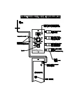
Page 20: ...BBQ07E COMPONENT LIST ...

Page 21: ... HDW088 46 1 Hot Rod Ignitor BAC199 F 8 Washer 1 4 Flat Zinc HDW130 47 8 Screw 8 x 5 Hex S Tap HDW119 A 8 Bolt 5 16 18 Socket Black HDW005 48 1 3 8 x 3 16 Thick Gasket BRN900 C 8 Nut 5 16 18 Hex Black HDW006 49 1 Draft Inducer Fan Assy FAN209 G 8 Washer 5 16 Lock Black HDW008 50 1 Power Cord 8 Nema 120v ELE203 E 16 Washer 5 16 Flat Black HDW007 51 1 Strain Relief ELE210 J 2 Bolt 1 4 20 x 310 Hex Z...

Page 22: ......

Reviews: