background image


Try not to damage the frame as you may have to move 
the machine long distances or store it for long 
periods.


2.2 HANDLING (Fig.2) 

As the machine is not heavy (Kg 16), it can be 
lifted and moved by a single person by gripping it   
from the machine body (5), duly clamped (see pint 2.3)   
   

2.3 TRANSPORT (Fig.2) 

It is necessary to low the saw body till the lower position 
and fix it to the base : it is sufficient to insert the pin 

U

 in 

the hole in the body , then lift the machine, gripping it as 
showed in Fig.2. 
For transport the machine, it is better to place it in the box 
it was when purchased. 
Ensure it is placed in the correct position indicated by the 
arrows on the packaging. 
Pay careful attention to the ideogram printed on the box as 
they provide all necessary information for palletization and 
stacking of boxes. 
Tying the load down with ropes or safety belts is 
raccomended during transportation to prevent the load 
from sliding or falling. 
 

2.4 POSITION/WORK STATION (Fig.3) 

Place the machine on a sufficiently flat workbench so that 
the machine has the better possible stability. 
In respect of ergonomic criteria during cutting operations, 
the workbench must be positioned at such a height that 
the clamp level is between 90 and 95 cm from the ground 
(see fig.3) 

ATTENTION: Make sure that the machine is placed in a 
working area with suitable environmental conditions 
and lighting. The general conditions of the working 
environment are of fundamental importance for 
accident prevention.   


2.5 ELECTRICAL CONNECTIONS 

Check that the mains to which the machine is connected is 
earthed in accordance with current safety regulations and 
that the power point is in good condition. 
Remember that there should be a magnetothermic 
protective device fitted upstream of the mains to protect all 
the conductors from short circuits and overloads.   
This protective device should be selected according to the 
electrical features of the machine listed below: 
Nominal voltage ................................. 1~,115 / 230V 


Nominal frequency ............................. 50/60Hertz 
Max programmed absorbed value ..... 3.8Ampere 
Nominal input power .......................... 1250Watt 
Power factor....................................... 0.93 
Nominal speed  ................................. 14.000-19.000rpm 
Insulation ........................................... Class B 
Type of service................................... intermittent S4-60 % 
In case of power failure in mains, while you wait for power 
to be restored there is no danger hazard may arise: in face, 
the electronic governor 

or main switch 

D

 is also 

equipped with a reset function which prevents the machine 
from restarting automatically. .............................................. 
The motor of your sawing machine (electronic version)is 

equipped with a protective heat circuit breaker which 
interrupts the power supply when the temperature of the 
coils rises too high. 
When the power supply is interrupted, wait for normal 
reset. 


3.0 ADJUSTING (Fig. 4-5-6-7-8)                                   


3.1 TENSION OF THE BLADE (Fig.4) 

Turn the handwheel

 B 

in a clockwise direction until it 

locks. 

If the tension is too high, the blade tends to escape 
from the guide. In this case, slacken the blade tension 
by turning of one/two turns the handwheel B in a anti 
clockwise direction. 


3.2 BAR STOP (Fig.5) 

Use the bar stop supplied if you have to do several cuts on 
pieces of the same length. 
In this way you do not have to repeat the same 
measurement each time. 
Screw rod 

E

 into the hole of the base and fasten it with 

nuts

 F

. Slacken the handwheel

 G 

and place the stop 

L

 at 

the correct distance from the blade. Tighten handwheel 

G


again.  
 

3.3 Cutting angle (Fig.6) 

The band saw can cut at an angle varying from 0 to 45 
degrees : it is sufficient to slacken the handle

 I

 and turn 

the swiwel support 

J

 towards the respective limit stops

 H 

and

 K

.  

For all intermediate angles, turn the swiwel support 

until 

the mark 

on the support matches the corresponding 

position on the plate. 
Then lock the rotating support 

J

 again. 


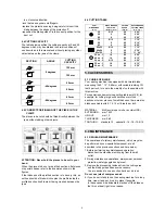
3.4 CUTTING SPEED (Fig.7) 

Two speed version 
Depending on the type of material and its section (see 
CUTTINGTABLE) you can choose two different cutting 
speed 60 or 80 m/min. by means of the switch 

N

.  

Electronic version 

Your sawing machine is equipped with CESC (Constant 
Electronic Speed Control), which allows gradual and 
continuous variation of the cutting speed , adapting it to 
the type and dimension of the material to be cut (see 
cutting table). 
To select the most suitable speed, use the speed control 
knob 

O

 to increase or decrease the speed as you require. 

Example: 

Stainless Steel:        30m/min.       position 1 
Common Steel:        40-60m/min.    position 2-3-4 
Allum.Alloy:                        80m/min.            position 6 
Pipes/sections:         70-80m/min    position 5-6 


4

Summary of Contents for 125

Page 1: ...PORTABLE BAND SAWING INSTRUCTIONS FOR USE AND MAINTENANCE SPARE PARTS MODEL 125 125 080605 R1 ...

Page 2: ...cal are Lead from lead based paints Crystalline silica from bricks cement and other masonry products Arsenic and chromium from chemically treated lumber Your risk from these exposures varies depending on how often you do this type of work To reduce your exposure to these chemicals Work in a well ventilated area and word with approved safety equipment such as those dust masks that are specially des...

Page 3: ... Fig Abb 2 Fi 9 10 6 4 11 12 13 g Abb 3 Fig Abb 1 K J I H M L G E Fig Abb 6 Fig Abb 5 A B Fig Abb 4 B Q R D P S Fig Abb 9 Q P Fig Abb 7 Fig Abb 8 Fig Abb 9 D N O D F Fig Abb 1 Fig Abb 3 Fig Abb 6 Fig Abb 5 Fig Abb 4 Fig Abb 9 Fig Abb 8 Fig Abb 7 1 ...

Page 4: ...ENSION OF THE BLADE 4 WITH USAGE POINTS 3 2 BAR STOP 4 Never underestimate the warnings ATTENTION CAUTION given in this manual 3 3 CUTTING ANGLE 4 3 4 CUTTING SPEED 4 In order to draw the user s attention and to preserve safety hazardous operation are preceded by symbols and notes that point out the danger and explain how to behave to avoid any risk 3 5 SLIDING BLADE GUIDE 4 3 6 BEARINGS BLADE GUI...

Page 5: ...ly in the clamp Always keep hands away from the working areas while the machine is moving before loading or unlading the part release the run button on the hand grip Do not force the machine unnecessarily excessive cutting pressure could cause rapid wear to the blade and negatively influence the performance of the machine in terms of finishes and cutting precision 1 6 NOISE CONDITIONS In normal co...

Page 6: ...0rpm Insulation Class B Type of service intermittent S4 60 In case of power failure in mains while you wait for power to be restored there is no danger hazard may arise in face the electronic governor O or main switch D is also equipped with a reset function which prevents the machine from restarting automatically The motor of your sawing machine electronic version is equipped with a protective he...

Page 7: ... performed the blade s cutting precision may be irreparably compromised If the limiter trips while the machine is in operation slightly decrease the cutting pressure in addition this enables to safeguard the blade life and performance and to obtain always a sharp and clean cut To obtain the best performance the bi metal blades fitted on your sawing machine must be run in for a short period For thi...

Page 8: ... 25x35 40x50 85x105 6 6 60 60 2 30 11 00 0 05 80 18 30 x s 1 40 x s 2 50 x s 5 14 8 12 80 80 0 15 0 50 30 x s 1 18 80 0 10 50 x s 2 14 80 0 30 5 0 ACCESSORIES 5 1 CHOISE OF BLADE Your sawing machine is equipped with a bi metal blade measuring 1440 13 0 65 mm with variable toothing 10t teeth per inch for use in the majority of cuts possible with this machine For special requirements see cutting tab...

Page 9: ...H and K retainers point 3 3 is inaccurate Set the retainers by unloosening the fastening screws and re positioning them Decrease cutting pressure Inaccurate cut squaring Excessive cutting pressure on pipes and section bars Check the cutting parameters blade toothing cutting speed in the cuts table point 4 6 Incorrect blade toothing in relation to the piece to cut Check blade guide adjustment point...

Page 10: ...8 ...

Page 11: ...9 ...

Page 12: ...10 ...

Page 13: ...11 ...

Page 14: ...d Screw M5x10L 8 18 111060 Bracket 2 19 HW004 Washer M6 2 20 HW005 Washer M8 2 21 111014 Knob 1 22 1 ET1244 Limit Switch 1 23 125048 Connecting Tube 1 24 125050A Blade 1440x13x0 65 8 12T 1 25 125017 Fixed Shaft 1 25 1 HT004 Flat Cross Head Screw M6x15L 3 26 111004 Drive Wheel 1 27 111072 Washer 1 27 1 111072A Washer 21 8 15 2 1 1 28 HE506 Hex Head Screw M5x10L 4 29 125036 Blade Back Cover 1 32 111...

Page 15: ... HK0609 2 59 111032 Washer 3 60 111005 Gear A 1 61 111044 Bushing 1 62 111006 Gear B 1 63 111033 Washer 1 64 CAHK0810 Bearing HK0810 1 66 CA6272RS Bearing 627 2RS 1 67 111007 Gear C 1 68 CA6202LLU Bearing 6202LLU 1 92 HW105 Spring Washer M8 6 93 HS242 Hex Socket Head Screw M8x20L 6 94 111059 Coaster 4 95 HW006 Washer M10x20x2t 2 96 HB804 Nut M10 1 97 HS935 Carriage Screw M10x33L 1 98 HN010 Hex Nut...

Page 16: ...er 2Speed 1 126 3 HS822 Cross Round Head Screw Ø4 0X40L 3 126 4 ET1247 2 Switch 3P 1 126 5 ET1156 ON OFF Switch KJD 17 220V 1 126 6 HS519 Cross Round Head Screw M5X10L 3 126S2 111093S2 Switch Assembly 1 126 2 111093C Cover 1 126 3 HS815 Cross Round Head Screw Ø3 5X35L 3 126 4 ET2147 Revolution Knob 1 126 5 ET1156 ON OFF Switch KJD 17 220V 1 126 7 111134 Speed plate 1 134 111066 Cable Clamp 6 135 H...

Page 17: ...DESCRIPTION SPECIFICATION QTY NOTE PARTS LIST MODEL NO 125 142 8 111068 Cover 1 142 9 HW104 Washer M6 1 142 10 HS227 Hex Socket Head Screw M6x5L 1 160 HW306 Star Washer M5 1 161 HS519 Cross Round Head Screw M5x10L 1 15 ...

Page 18: ......

Page 19: ......

Page 20: ...SERIAL No PLEASE WRITE DOWN THE SERIAL NO ON THIS BLOCK FROM THE NAME PLATE AFTER YOU RECEIVE THIS MACHINE ADDRESS ...

Reviews: