5 |
P a g e
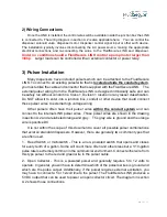
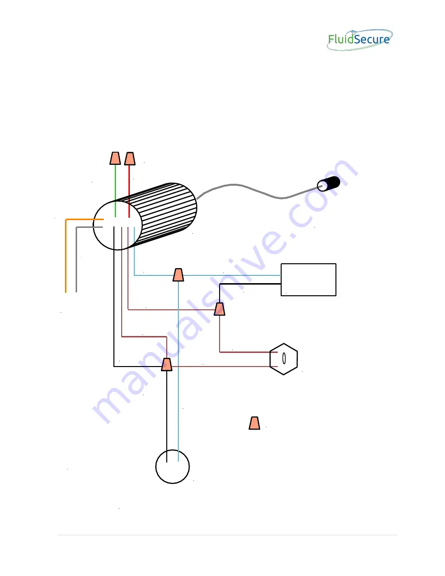
2) Wiring Connections
The installation typically involves disconnecting the AC power supply wring (generally
that comes from a nearby building or power source) from the dispenser and re-routing it
through the supplied conduit parts that are supplied as part of the LINK kit and re-
connecting the wires to the FluidSecure LINK and dispenser.
Under no condition
should a FluidSecure LINK control a pump motor larger than 3/4hp.
Larger loads
can be controlled with an external contactor or power relay.
DISPENSER
Solenoid/
Motor
MANUAL
OVERRIDE
SWITCH
FLUIDSECURE LINK
POWER
FROM
BUILDING
or Dispenser
WIRENUTS
BROWN
BROWN
BROWN
BROWN
BLACK
120VAC/
240VAC
BLACK
BLACK
WHITE
WHITE
WHITE
(Neutral)
RED
(+12VDC)
GREEN
(DC Gnd)
ORANGE
GRAY
INTERNAL
PULSER
CONNECTIONS
NOTE:
Two brown wires coming
from the FluidSecure
unit are dry contacts of
a 16 amp mechanical
relay and are not electrically
connected internally in the
FluidSecure Link
FluidSecure Link Wiring Diagram
Alternate power input to run Link from a 12VDC source
External
Link
Pulser
Connector


