102
TRAK Machine Tools
Southwestern Industries, Inc.
ProtoTRAK SMX, K2, K3 & K4 & Retrofit Safety, Installation, Maintenance, Service and Parts List Manual
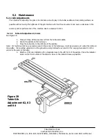
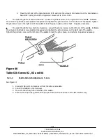
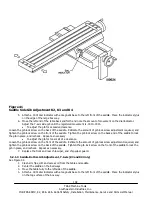
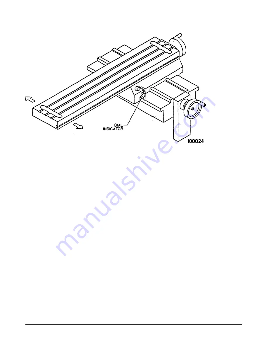
Figure 41
Saddle Side Gib Adjustment K2, K3 and K4
5.
Attach a .0001 dial indicator with a magnetic base to the left front of the saddle. Place the indicator stylus
on the edge of the large box way.
6.
Move the left end of the table back and forth and note the amount of movement on the dial indicator.
Adjust the Y-axis side gib until the registered movement is .0010-.0015.
To adjust the gib for excessive clearance:
Loosen the gib lock screw on the back of the saddle. Estimate the amount of gib lock screw adjustment required, and
tighten the gib lock screw on the front of the saddle. Tighten the gib lock screw on the back end of the saddle to lock
the gib in place, and recheck. Repeat as necessary
To adjust the gib for too small of a clearance:
Loosen the gib lock screw on the front of the saddle. Estimate the amount of gib lock screw adjustment required, and
tighten the gib lock screw on the back of the saddle. Tighten the gib lock screw on the front of the saddle to lock the
gib in place, and recheck. Repeat as necessary.
7.
Replace the front and rear chip wiper, and chip wiper guard.
5.2.1.3 Saddle Bottom Gib Adjustment, Y-Axis (K3 and K4 Only)
See Figure 42.
1.
Clean all chips, dirt and excess oil from the table and saddle.
2.
Center the saddle on the bed ways.
3.
Move the table fully to the left side of the saddle.
4.
Attach a .0001 dial indicator with a magnetic base to the left front of the saddle. Place the indicator stylus
on the top surface of the box way.

