104
TRAK Machine Tools
Southwestern Industries, Inc.
ProtoTRAK SMX, K2, K3 & K4 & Retrofit Safety, Installation, Maintenance, Service and Parts List Manual
5.2.2.1 X, Y, Z and Quill Calibration
Calibration is used teach the machine a known distance. We typically calibrate our machines over a 150 mm distance.
There is no limit to how far you can calibrate the machine.
1.
If you have installed TRAK Sensors, move each axis through its travel 4-6 times in order to allow the gage
wheel to establish its track.
2.
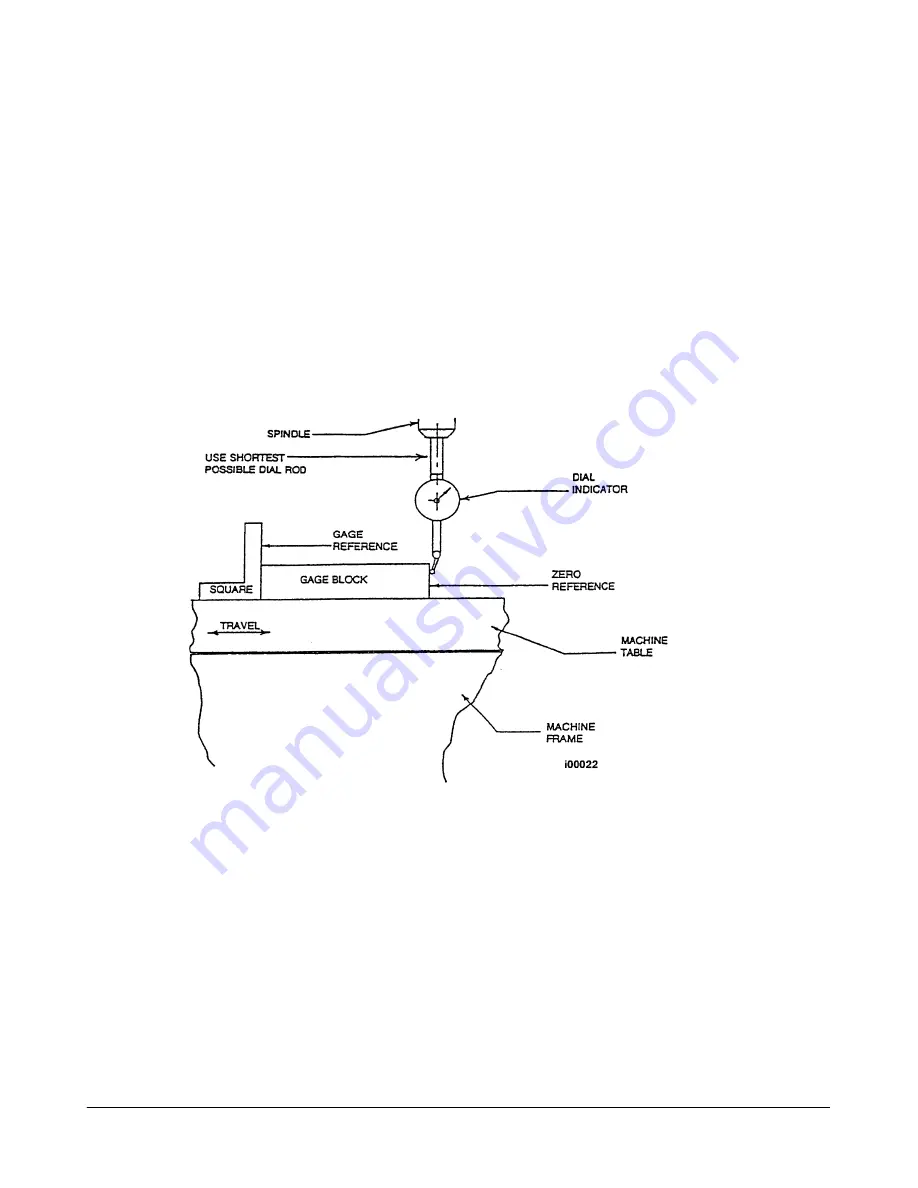
Set-up a gauge block or standard and indicate it parallel to the axis you are calibrating.
Note: Put the display in Inch or mm to match your gage block. Recommended gage blocks are:
X and Y -- 150mm or 6”
Z -- 75 mm or 3”
3.
Set a 0.0001” indicator in the spindle and move it up to one side of the gage block or standard.
4.
Go to setup mode, go to section “B” and press CODE 123.
5.
Select the axis you want to calibrate X, Y or Z. For the quill press the F1 key labeled QUILL. The Z key is
used to calibrate 3 axis machines only.
6.
Follow the instructions on the screen to complete calibration.
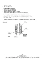
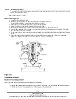
Figure 43
Calibration Set-Up
5.2.2.2 Backlash Compensation
Code 11: Set X or Y backlash constant
Note: this procedure is on systems with TRAK Sensors or Glass Scales only.
Go to setup mode, go to section “B” and press CODE 11. Refer to service code section for further
explanation.
Code 127: Set X or Y Backlash Constant
Note: this procedure is only for systems without TRAK Sensors or Glass Scales.

