107
TRAK Machine Tools
Southwestern Industries, Inc.
ProtoTRAK SMX, K2, K3 & K4 & Retrofit Safety, Installation, Maintenance, Service and Parts List Manual
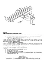
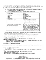
5.2.3.3 Back to Front Adjustment – K2/K3 only
1.
Make sure the table has been clean and the gibs are adjusted properly.
2.
Mount a dial indicator in a tool holder and mount in the quill.
3.
Adjust the Y-axis so that the spindle is in the center of the table.
4.
Adjust the knee so that the dial indicator will reach the table and lock the 2 clamps on the knee.
5.
Move the dial indicator to 6 o’clock position and adjust the face so the needle is zero.
6.
Do a series of sweeps from 6 o’clock to 12 o’clock and check for the repeatability of the setup. The
head should be trammed as close as possibility to ± 0.0005”
7.
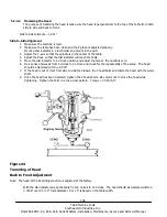
Loosen the three bolts and adjust the tram with the bolt mounted on the top of the ram.
Once the head has been trammed tighten the three bolts. Be careful not to move the head while tightening. Tighten
the bolts a little at a time. (Note: the head must droop down rather than up because tool pressure will take care of the
extra 0.0005”.)
5.2.4 Limit Switch Option
See figures 64 and 65 in section 7.
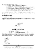
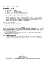
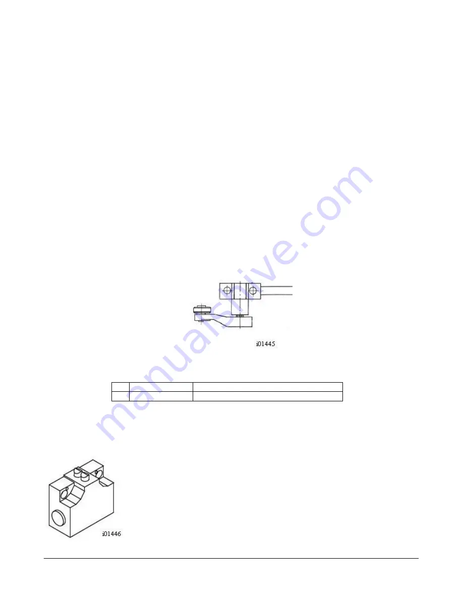
The limit switch option design was changed from when we first released the SX control. Early limit switch kits came with
a single input limit switch as shown in the figure.
Figure 45 – 1 Input Limit Switch
#
Part Number
Description
1
16117
Limit Switch Assembly with cable
The latest design consists of a limit switch with 2 inputs as shown in the figure. This means 1 input for each direction.
On machines with electronic handwheels, when you hit a limit the EHW will only allow you to move the machine in the
direction away from the limit switch. This will prevent the user from damaging the machine by hitting a hard stop.

