108
TRAK Machine Tools
Southwestern Industries, Inc.
ProtoTRAK SMX, K2, K3 & K4 & Retrofit Safety, Installation, Maintenance, Service and Parts List Manual
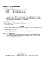
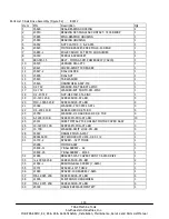
Figure 45-1– 2 Input Limit Switch
Part number – 22408
#
Part Number
Description
1
22408
Limit Switch (no cable)
2
22551-1
Limit Switch Assembly with cable – right
3
22551-2
Limit Switch Assembly with cable – left
5.2.4.1 X-Axis Limit Switch-Stop Installation and Adjustment
The limit switch-stops/cams for the X-axis are mounted to the front side of the table and can be adjusted
along the length of the T slot. Each limit switch-stop must be set to a specific distance from the end of the
table in order to maximize travel and simultaneously prevent serious damage to the machine in the event of
a crash. All limit switches are set at the factory for maximum travel.
Procedure for Setting X Limit Switch
1.
Loosen the stops or cams on each side of the table.
2.
Slide each stop or cam within the T-slot to the end of the table.
3.
Slowly move the table to one side by hand until the end of the travel is reached.
4.
In DRO mode set X = 0 ABS.
CAUTION!
The limit switch must be triggered a minimum of ½” before the machine reaches its travel limits in both
directions. This allows sufficient room for the servomotors to stop when the limit switch is hit at 150 ipm.
5.
Using the DRO display, back the table off 1/2".
6.
Lock the limit switch bracket in place.
7.
Jog the table at 100ipm to each side and verify that the limit switch is working properly. Also, make sure that the
table does not exceed its travel and crash.
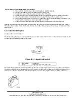
5.2.4.2 Y Axis Limit Switch-Stops
The limit switch-stops for the Y-axis are mounted on the side of the knee. The limit switch is triggered by
hitting the cam stop on the saddle. The cam is placed to ensure maximum travel. The 2 input limit switch
design allows for slight adjustment of each cam.


