111
TRAK Machine Tools
Southwestern Industries, Inc.
ProtoTRAK SMX, K2, K3 & K4 & Retrofit Safety, Installation, Maintenance, Service and Parts List Manual
7.0 Installation Procedures
7.1 X and Y Ball Screw Installation
7.1.1 Removing the Table and Leadscrews
Note: Before removing any of the assemblies as directed below, crank the table all the way to the right or left in order to
be able to position the lift table next to the machine.
1.
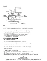
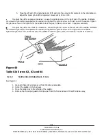
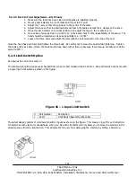
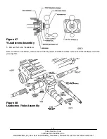
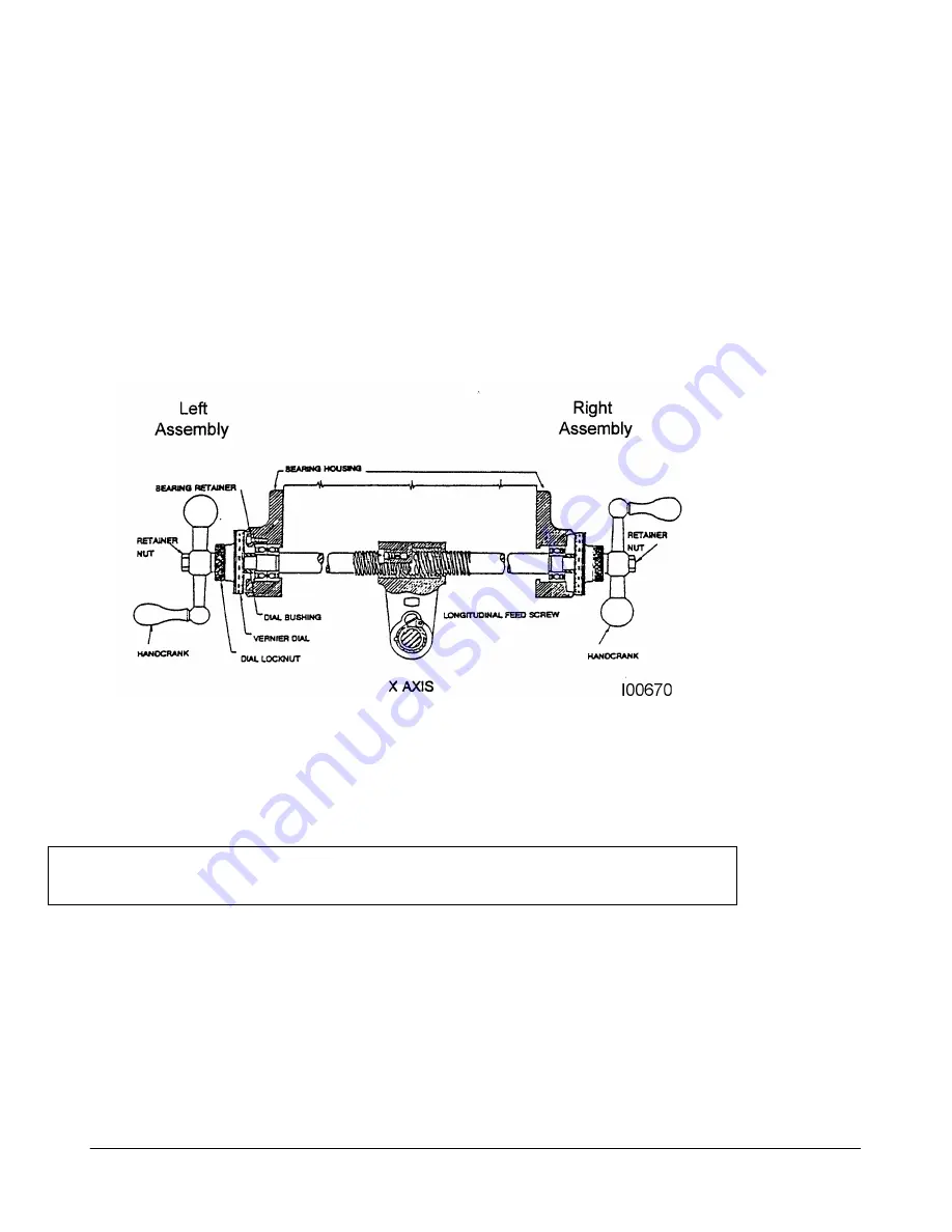
Remove the left and right bearing assemblies. Save the parts removed from the right side for use in installing
the X-Axis ball screw.
Note: If the machine has a power feed on the right end, save the left end assembly to mount later to the right end.
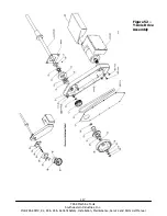
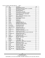
Figure 46
X Leadscrew Assembly
2.
Center the table and remove the X gib.
3.
Slide the machine’s table onto a lift table and move it away from the machine.
CAUTION!
When removing the table, make sure it does not cock or it may
break the dovetails as it slides out.
4 .
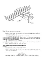
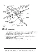
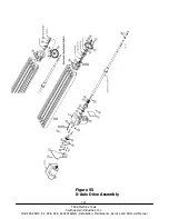
Crank the saddle all the way forward and remove the Y-axis bearing assembly.
Save the vernier dial for use with the Y-axis ball screw.

