123
TRAK Machine Tools
Southwestern Industries, Inc.
ProtoTRAK SMX, K2, K3 & K4 & Retrofit Safety, Installation, Maintenance, Service and Parts List Manual
33.
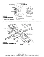
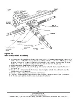
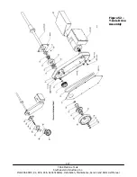
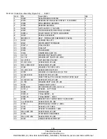
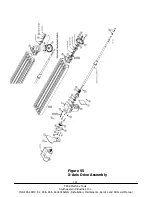
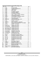
Install the left end assembly items as shown in Figure 55.
34.
Slide the table so that the left end of the table is approximately over the left end of the ball screw and install the
drive housing onto the table with the four 3/8 -16 x 2 1/2” socket head cap screws.
35.
Slide the table to the right and secure the drive housing bracket to the bearing housing per Figure 55.
36.
Install the rest of the items of Figure 55 and tighten 1/2-20 nut to 50 ft/lb.
37.
Screw the ball screw so that the table is positioned with the right side of table almost flush with the right edge of the
saddle.
Note: Temporarily install the 1/2 - 20 nut on the right of the ball screw and use this to turn the ball screw.
38.
Install the original machine right side assembly and the SWI provided handwheel as per Figure 55.Tighten
1/2-20 nut to 50 ft/lb. (If the machine had a power feed, use the hardware from the left side).
Note: if the ball screw requires a ball screw extension see Step 39 - “Installing ball screw extensions”. Otherwise go to
Step 40.
39.
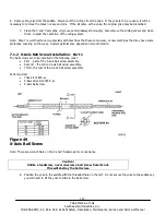
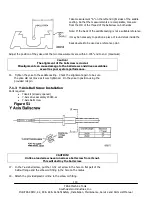
Ball screw Extension Installation
1.
Slide bushing onto end of ball screw.
2.
Screw threaded extension snugly onto ball screw.
3.
Tighten setscrew (inside of threaded extension) finger-tight.
4.
Back off the threaded extension 1/16 of a turn.
5.
Tighten setscrew.
6.
Using two wrenches, tighten the threaded extension to the ball screw.
Note: The 6” extension uses a pin inside the threaded extension in addition to the setscrew.
40.
Make a preliminary gib adjustment for each of the table and saddle gibs. Tighten the gibs until there is a noticeable
drag on the table and saddle and then gradually loosen until the drag goes away and the motion is smooth again.
There is additional information on gib adjustments in Section 5.

