128
TRAK Machine Tools
Southwestern Industries, Inc.
ProtoTRAK SMX, K2, K3 & K4 & Retrofit Safety, Installation, Maintenance, Service and Parts List Manual
Caution!
Do not drill through the threaded quill stop rod.
7.4 Cable Breakout Box Mounting
The cable breakout box can come in 2 different configurations, one with auxiliary functions and one without. The
physical size of the box is the same for both versions. The only difference is the 2 auxiliary ports found on the right side
of the box. The auxiliary function box will have a 110 V outlet and a 4-pin amp connector to run an indexer. Mount the
cable breakout box on the rear of the machine as shown in Figure 4 in Section 2. It will mount with the use of (3) M6 x
20 SHCS. You may need to add washers to the back of the box to offset it from the machine it case of casting
interference.
7.5 Z-Axis Glass Scale Installation
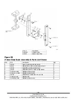
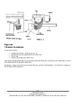
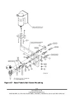
See Figure 58.
1.
Check the tram of the head in the X direction. If it is within a few thousands then continue on. If not tram.
2.
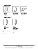
Mount the upper mounting bracket loosely to the upper mounting surface of the head with a 10-32 cap screw.
3.
Mount the lower mounting bracket loosely to the lower mounting surface of the head with a 10-32 cap screw.
4.
Install the 2 each, 6-32 leveling screws to each mounting bracket.
5.
Mount the scale loosely to the mounting brackets with a 1/4-20x 1/2” bhcs and M6 washer.
6.
Indicate the front of the scale and the right side of the scale to within .005” over the travel of the quill. Tighten
the bracket mounting screws and use the leveling screws to adjust the alignment.
7.
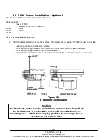
Mount the readerhead bracket to the quill stop knob with the pin and 1/4-20x 1” shcs.
8.
Remove the readerhead cover plate and position the readerhead bracket so its holes line up with the holes in
the readerhead. Use shims as necessary between the pin and bracket if the holes do not line up side-to-side
with the readerhead holes. There should be a gap of 0.030”-0.180” between the readerhead and bracket.
Kit Variation: some scale brackets require the transfer of the hole pattern of the readerhead to the readerhead bracket.
9.
The rest of the scale installation is the same as the X-axis, Steps 5 through 7.
Key Notes:
10.
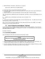
Move the readerhead up and down the glass scale and make sure the gap is consistent between the readerhead and
the glass scale. Tighten the screw to the quill stop knob.
11.
Remove the red head securing plate.
12.
If the gap is not consistent between the readerhead and the glass scale when moving the quill up and down then
adjust the angle of the scale to make the gap consistent.
Warning
The gap must be no larger than 0.060” between the readerhead and glass scale.

