background image


186 

TRAK Machine Tools 

Southwestern Industries, Inc. 

ProtoTRAK SMX, K2, K3 & K4 & Retrofit Safety, Installation, Maintenance, Service and Parts List Manual 


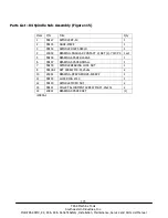
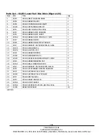
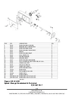
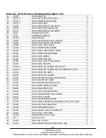
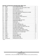
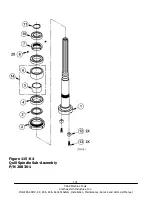
Parts List – K2/K3 Lower Vari-Disc Drive (Figure 123) 

Item  P/N 

Title 

Qty 

VS50 

FRU-K3-BELT HOUSING BASE 

VS59 

FRU-K3-BRAKE BLOCK 

VS58 

FRU-K3-TURNING BLOCK SHAFT 

VS103 

FRU-K3-RETAINING RING Ø 7 

VS51 

FRU-K3-SET SCREW M6-1.0X6L 

VS53 

FRU-K3-BRAKE LOCK BUSHING 

VS52 

FRU-K3-BRAKE LOCK SHAFT 

VS52-2 

FRU-K3-BRAKE LOCK PIN DIA 3 X 5/8"L 

VS47 

FRU-K3-BRAKE SHOE 

10 

VS48 

FRU-K3-BRAKE SHOE PIVOT SLEEVE 

11 

VS17 

FRU-K3-SOCKET CAP SCREW M6-P1.0x35L 

12 

VS17-1 

FRU-K3-WASHER Ø 6 

13 

VS17-2 

FRU-K3-NUT M6-P1.0 

14 

VS49 

FRU-K3-BRAKE SPRING 

15 

VS122 

FRU-K3-WASHER DIA 3.3 

16 

VS120 

FRU-K3-SCREW-PAN HEAD PHILIP 5-40NC 

17 

VS46 

FRU-K3-BRAKE BEARING CAP 

18 

VS43-1 

FRU-K3-BALL BEARING 6010ZZ 

19 

VS14 

FRU-K3-SOCKET CAP SCREW M5-0.8x12L 

20 

VS45 

FRU-K3-STATIONARY DRIVEN VARIDISC 

21 

VS70 

FRU-K3-SPINDLE PULLY ASSY 

22 

VS100 

FRU-K3-SPINDLE PULLY SPACER 

23 

VS71 

FRU-K3-KEY 8x7x20L 

24 

VS97 

FRU-K3-SNAP RING Ø 40 

25 

VS50-1 

FRU-K3-DUST COVER 

26 

VS50-2 

FRU-K3-SCREW-FH-PH-STL-BO M6-1.0X6L 

27 

24055 

BRAKE SHOE ASSY 

(1) 

i20778-5 


Summary of Contents for ProtoTRAK SMX K2

Page 1: ...Maintenance Service Parts List Manual Document P N 24319 Version 082718 2615 Homestead Place Rancho Dominguez CA 90220 5610 USA T 310 608 4422 F 310 764 2668 Service Department 800 367 3165 e mail sal...

Page 2: ...prior written permission of Southwestern Industries Inc While every effort has been made to include all the information required for the purposes of this guide Southwestern Industries Inc assumes no...

Page 3: ...and or Moving the Machine 14 2 9 Cleaning 16 2 10 Leveling Leveling Tolerance is 0005 10 16 2 11 Electrical Connection 18 2 11 1 Phase Converters 21 2 11 2 Flange Disconnect Transformer Optional 21 2...

Page 4: ...3 11 E Stop Error 47 3 3 12 Limit Switch Error Optional 48 3 4 Problem with the Measurements 48 3 4 1 X Y and Z Axis Measurements Do Not Repeat 48 3 4 2 X Y and Z Axis Measurements Are Not Accurate 50...

Page 5: ...4 9 2 Machine Set up Codes 70 4 9 3 Diagnostic Codes 72 4 9 4 Operator Defaults Options Codes 73 5 0 Procedures for Replacements Maintenance 74 5 1 Replacements 74 5 1 1 Servo Motor Replacement 74 5...

Page 6: ...on Part 1 113 7 1 3 Y Axis Ball Screw Installation 115 7 1 4 X Axis Ball Screw Installation Part 2 120 7 2 Motor Servo Driver Installation 124 7 2 1 X Axis Motor Servo Driver Installation 124 7 2 2 Y...

Page 7: ...nual 8 3 Installation of the Motor and Remaining Components 142 8 4 Lagun Z Axis Cutout 148 9 0 Introduction to Self Service 149 9 1 When You Have a Service Problem 149 9 1 1 Communication with the SW...

Page 8: ...afety Publications Refer to and study the following publications for assistance in enhancing the safe use of this machine Safety Requirements for Manual Milling Drilling and Boring Machines with or wi...

Page 9: ...rotoTRAK SMX K2 K3 K4 Retrofit Safety Installation Maintenance Service and Parts List Manual Safety Information Labels Used On The TRAK K Milling Machines It is forbidden by OSHA regulations and by la...

Page 10: ...deface destroy or remove any of these labels Power Requirements at 220 and 440 Volts 3 phase 60 Hz SMX K2 K3 SMX K4 Vari speed Head Spindle Control Vari speed Head Spindle Control Overload Setting 22...

Page 11: ...your hands Stop the machine spindle and ensure that the CNC control is in the stop mode Before changing tools Before changing parts Before you clear away the chips oil or coolant Always use a chip sc...

Page 12: ...grity of cutting tools and their holders Use proper length for the tool 24 Large overhang on cutting tools when not required result in accidents and damaged parts 25 Handwheels must have the crank fol...

Page 13: ...ion procedure 2 1 Floor Plan Layout Space Requirements K2 K3 K4 Figure 1 Machine Footprints K2 K3 K4 Weight approximate net 2200 lbs 2800 lbs 3600 lbs Weight approximate shipping 2500 lbs 3100 lbs 390...

Page 14: ...rts List Manual K2 K3 K4 Table Size 9 x 49 10 x 50 10 x 50 T Slots number x width 3 x 5 8 3 x 5 8 3 x 5 8 Dimension G 86 87 92 Dimension G Min 65 65 73 Dimension H Min 56 64 64 Dimension H Max 67 78 7...

Page 15: ...at this time that can be attributed to the transportation or improper handling moving of the machine 2 3 Shortages Inventory Checklist _____ Machine check model and serial number ______ Manual drawba...

Page 16: ...ower to the machine and to the pendant 10 Load master and slave software from software upgrade disk or USB The pendant may or may not have the latest software loaded Retrofits only 11 Lubricate all th...

Page 17: ...32 x 16 x 16 32 x 16 x 16 5 Quill Travel maximum 5 5 5 Quill Diameter 86 mm 86 mm 100 mm Spindle Taper R8 R8 40 taper Speed Range 60 4200 RPM 60 4200 RPM 70 3950 RPM Optional Spindle Control Speed Ran...

Page 18: ...ensure smooth accurate contours without backlash Feedrate override of programmed feedrate and rapid Polycarbonate sealed membrane and gasket sealed control enclosure to lock out contamination 10 colo...

Page 19: ...d Parts List Manual Figure 3 Parts List Shown Knee Mill Component Identification Item Part Number Description SMX K2 K3 SMX K2 K3 Spindle Control SMX K4 SMX K4 Spindle Control 1 20819 24162 20820 2416...

Page 20: ...Number Description SMX K2 K3 SMX K2 K3 Spindle Control SMX K4 SMX K4 Spindle Control 1 220V 20676 440V 20676 24060 1 220V only 220V 20676 1 440V 20676 24060 2 220V only Electrical Box 2 24999 24999 24...

Page 21: ...with protective sleeving min 3 4 diameter or a 3 ton sling position sling loops on machine as shown in Figure 5 2 Use cardboard pieces or other suitable protective sheets on both sides of the machine...

Page 22: ...15 TRAK Machine Tools Southwestern Industries Inc ProtoTRAK SMX K2 K3 K4 Retrofit Safety Installation Maintenance Service and Parts List Manual Figure 5 Lifting the Machine...

Page 23: ...damage to the TURCITE surface of slideways can occur 4 Be certain the table saddle and spindle move freely and smoothly over their entire length 2 10 Leveling Leveling Tolerance is 0005 10 1 Set the m...

Page 24: ...toTRAK SMX K2 K3 K4 Retrofit Safety Installation Maintenance Service and Parts List Manual I00138 Figure 6 Placement of Levels Figure 7 Parts List Shown Leveling Screws Item P N Title 1 FC112 LEVEL SC...

Page 25: ...s all local codes and regulations Incoming 220 or 440 volt power connects to the machine through the electrical box located on the back of the column The power cable enters the black box through a hol...

Page 26: ...RAK Machine Tools Southwestern Industries Inc ProtoTRAK SMX K2 K3 K4 Retrofit Safety Installation Maintenance Service and Parts List Manual Figure 8 Wiring K2 K3 or K4 Non Spindle Control Not for Retr...

Page 27: ...ts List Shown Wiring the K2 K3 or K4 Spindle Control See Figure 117 in the rear of the manual for a more detailed breakdown of parts TRAK Machine Tools recommends the machine be earth grounded by driv...

Page 28: ...system The electrical load on the machine will vary based on the type of cut taken Static phase converters can only be used on machines with a non varying load The phase converter for the K mill machi...

Page 29: ...ne Tools Southwestern Industries Inc ProtoTRAK SMX K2 K3 K4 Retrofit Safety Installation Maintenance Service and Parts List Manual Figure 10 Flange Disconnect Transformer Option P N 23440 220 23440 1...

Page 30: ...NEMA STD 15A 125V 4 13 21871 CONNECTOR 4 POSITION SIZE 11 1 14 23297 1 CONNECTOR REVERSE SEX 13 7 CPC 1 16 21820 FUSE HOLDER 2 17 21824 5 FUSE 3AG SLOW BLOW 1 18 21830 12 FUSE TYPE 3AB 12A SLO BLO 1 1...

Page 31: ...24 TRAK Machine Tools Southwestern Industries Inc ProtoTRAK SMX K2 K3 K4 Retrofit Safety Installation Maintenance Service and Parts List Manual...

Page 32: ...ts to hook up an air line to clean chips Remove the plug to gain access to this port If the machine has an auxiliary function option then the machine will include an air solenoid as shown below The ai...

Page 33: ...e machine turned off plug in the connectors that are bundled on the pendant arm Each cable mates to only one connector on the pendant display back panel Use the key on the pendant to match up the conn...

Page 34: ...wer cables consist of the 3 110 volt motor cables and 2 110 volt power cables for the pendant and a coolant pump or solenoid power cable The logic cables are used to carry encoder signals between the...

Page 35: ...TRAK Machine Tools Southwestern Industries Inc ProtoTRAK SMX K2 K3 K4 Retrofit Safety Installation Maintenance Service and Parts List Manual Figure 14a Pendant Right Side P N 24000 1 Replaced by 24000...

Page 36: ...29 TRAK Machine Tools Southwestern Industries Inc ProtoTRAK SMX K2 K3 K4 Retrofit Safety Installation Maintenance Service and Parts List Manual Figure 14b Pendant Right Side USB Ports P N 24000 7...

Page 37: ...30 TRAK Machine Tools Southwestern Industries Inc ProtoTRAK SMX K2 K3 K4 Retrofit Safety Installation Maintenance Service and Parts List Manual Figure 15 Cable Connections Diagram Non Spindle Control...

Page 38: ...arts List Manual Parts List Cable Connection Figure 15 Non Spindle Control Item Part Number Description K2 K3 K4 1 220V 20676 440V 20676 220V 20676 1 440V 20676 1 Electrical Box 2 21856 Cable Assembly...

Page 39: ...TRAK Machine Tools Southwestern Industries Inc ProtoTRAK SMX K2 K3 K4 Retrofit Safety Installation Maintenance Service and Parts List Manual Figure 16 Cable Connection Diagram with Spindle Control Opt...

Page 40: ...ength of its travel to ensure lubrication reaches all surfaces 2 At the beginning of each day check the oil level in the system If low fill with Mobil Vactra Oil No 2 or equivalent CAUTION Failure to...

Page 41: ...34 TRAK Machine Tools Southwestern Industries Inc ProtoTRAK SMX K2 K3 K4 Retrofit Safety Installation Maintenance Service and Parts List Manual Figure 17 Knee Mill Lubrication...

Page 42: ...CREW NUT M8 X 1 0 FEMALE 3 12 9012 ADAPTER 1 13 9013 SLEVE 4 1 mm I D 18 i00889 2 15 2 Head Lubrication Note the white head represents the K4 40 taper head Once Each Week 1 Add SAE 30 or 30W oil to th...

Page 43: ...block program from the ProtoTRAK SMX flash disk which is Part Number Euclid 2 axis PT4 It is found under the PT4 folder followed by the SWI TEST PROGRAMS folder 4 Use an edge finder to set Absolute 0...

Page 44: ...37 TRAK Machine Tools Southwestern Industries Inc ProtoTRAK SMX K2 K3 K4 Retrofit Safety Installation Maintenance Service and Parts List Manual Figure 18 Euclid Test Block P N 15537 1...

Page 45: ...etup Section 4 1 Table Saddle or Knee Locks are locked Make sure the Table and Saddle Locks are unlocked Never use gib locks with a CNC machine Inadequate or no Lubrication to Ballscrews and Way surfa...

Page 46: ...g to the Sensor or Glass Scale Installation procedures Check for any loose brackets or misalignment etc Also check to make sure the Sensor or Glass Scale assemblies are functioning correctly See TRAK...

Page 47: ...to repeat within the resolution of the displayed DRO numbers of 0 0005 Do the following Service Code Code 33 Software Identification This is needed if you call SWI Customer Service Code 123 Calibrati...

Page 48: ...ns with codes 321 and 322 The home positions or tools are not set correctly See the Controls Programming Operations and Care manual The Sensor or Glass Scale is not reading See TRAK Sensors or Glass S...

Page 49: ...ter Pendant failed See Computer Pendant diagnostics Section 4 3 3 2 4 Axis Motor Motion Is Not Smooth While under motor power the motion is not smooth The motion appears to be rough or jerky Do the fo...

Page 50: ...on X and Y Gibs are not adjusted properly Check the adjustment of the X and Y Gibs using the X and Y Gib adjustment procedures Gibs not making good contact Pull gibs out and mark with a blue die to ch...

Page 51: ...has strange characters horizontal bars or other unfamiliar images or the display continually rolls Possible Cause Check This Computer Pendant failed See Computer Pendant Section 4 3 3 3 3 Keyboard Lo...

Page 52: ...le Cause Check This Improper Boot up Shut down the system and wait 10 seconds before rebooting Floppy Disk failure The Floppy Disk may be bad See if the Floppy Disk can be read by a Personal Computer...

Page 53: ...peration the system shuts off and will not turn back on Possible Cause Check This Fuse blown in pendant Remove fuse and check continuity Poor wiring and cable connections Check for any loose wiring Al...

Page 54: ...es will not work Do the following service code and procedures Code 33 Software Identification This is needed if you call SWI Customer Service Possible Cause Check This Bad 110VAC Coolant or solenoid r...

Page 55: ...as necessary 2 Press the Mode or Return key to reset the control 3 Press the DRO key to enable the machine to once again jog Possible Cause Check This Limit switch jumpers in cable breakout box are m...

Page 56: ...on procedures Check for any loose brackets or misalignment etc Also check to make sure the Sensor or Glass Scale assemblies are functioning correctly Use service codes 304 for X and 305 for Y to turn...

Page 57: ...4 305 Turns off X and Y sensor or scale Possible Cause Check This Motor Encoder not counting See Motor diagnostics not applicable with Glass Scale option Single feedback only Glass Scale or Sensor Fai...

Page 58: ...ition and tension of the Drive Belt Cut more than the machine is capable Check width and depth of cut Spindle Drive Thermal Overload Relay has tripped IOUT Current Out located on the Spindle Drive can...

Page 59: ...wired for 220 volts 440 volts will ruin electrical components in the machine These components will not be covered under warranty Possible Cause Check This Wrong voltage Check the voltage to the machin...

Page 60: ...lar job Use the table below to try to pinpoint the possible cause Also try to pinpoint the noise by seeing if it exists in high low or neutral For example if the noise is evident in neutral then this...

Page 61: ...e upper bearing plate above the spindle This will unload the bearing If the noise goes away then this bearing should be replaced Verify nosepiece is tight on bottom of spindle To check if the nosepiec...

Page 62: ...en using the CNC to machine never tighten the gib locks X and Y gibs loose See Gib Adjustment Section 5 2 1 Taper on straight Y moves Poor finish Circle out of round When machine hasn t been serviced...

Page 63: ...way surfaces 4 1 4 Machining Set Up The machining set up itself is always something that can greatly influence the performance of the your mill The following are some things to keep in mind Problems W...

Page 64: ...e machine down from fully assembled and point out the areas to look at specifically 3 Check that the belt is properly tightened A loose belt can lead to excessive backlash compensation values on motor...

Page 65: ...gnment X axis there are 3 components that can cause misalignment the yoke the left side bearing housing bracket and the right side bearing housing Yoke the yoke is aligned at the factory and pinned in...

Page 66: ...cable connections to LCD distribution board and computer module Make sure the power is turned off before doing so Faulty E stop switch It can be stuck open or closed pressed If it is stuck closed the...

Page 67: ...eplacing the motor due to a bad motor encoder it is a good idea to check the cables that take those signals back to the pendant If these signals are not getting back to the pendant then the axis will...

Page 68: ...le place a 0 001 indicator on the bed ways and on top of the scale extrusion Move the table along its full travel from one end to another to verify it is aligned If the scale is misaligned loosen the...

Page 69: ...s to turn off the sensor on the axis in question This will allow the system to run only on the motor encoders If the fault continues then the sensor was not the problem Turn the sensor back on See the...

Page 70: ...lly have crinkles in the small triangle shaped plates on the front and back Use a bubble level or an indicator to adjust the puller screws so that the base is parallel to the running surface Inspect t...

Page 71: ...ons This module is located on the back side of the machine It consists of 3 motor connections 3 limit switch connections 3 encoder connections and an E stop connection Machines with an auxiliary funct...

Page 72: ...to control the spindle motor 2 4 output 110 volt outlets 1 outlet is used to power the pendant 1 is used to power the lube pump and is turned on based on the spindle being on 2 additional outlets 3 2...

Page 73: ...on When the E stop is pressed this light should go off 2 LED labeled LATCH RELAY this light should be on when the spindle is running or if the spindle is not running and the fwd rev switch is in the o...

Page 74: ...ls Southwestern Industries Inc ProtoTRAK SMX K2 K3 K4 Retrofit Safety Installation Maintenance Service and Parts List Manual Figure 21 LEDs on Spindle Control Board Figure 20 Schematic Diagram of Spin...

Page 75: ...68 TRAK Machine Tools Southwestern Industries Inc ProtoTRAK SMX K2 K3 K4 Retrofit Safety Installation Maintenance Service and Parts List Manual...

Page 76: ...ODE 142 Save Configuration file to an external drive This code allows you to save your configuration file to a floppy disk or external drive The configuration file consists of items such as calibratio...

Page 77: ...iction characteristics of the machine by sending a graduated series of motor signals and observing the results The process takes less than 30 seconds to run It is both a diagnostic routine that displa...

Page 78: ...HICH DIRECTION PLUS If you want to run in the plus direction press INC SET If you want to run in the minus direction press then INC SET 5 In the conversation line it will say PRESS GO Press Go after y...

Page 79: ...le turned on only 3 both X and Y sensor or glass scale turned on 4 9 2 8 Code 305 Toggles Y sensor or glass scale on off This service code toggles the Y sensor or glass scale on or off See Code 304 fo...

Page 80: ...top The file will capture data until the file reaches a size of approximately 600 Kb At this time the file is saved to a backup file and the original file is cleared and data is once again captured On...

Page 81: ...power is disconnected from the machine The servo drivers are run by 110 VAC There is possibility of death by electrocution The Servo Driver for each axis is integrated into the servo motor casting WAR...

Page 82: ...emove the 6 10 32 x 3 8 Pan Phillips Head Screws and 4 10 32 x 3 8 FHCS securing the computer module to the LCD enclosure 6 Pull the computer module a few inches and stop Pulling the computer module t...

Page 83: ...76 TRAK Machine Tools Southwestern Industries Inc ProtoTRAK SMX K2 K3 K4 Retrofit Safety Installation Maintenance Service and Parts List Manual Figure 23 Computer Module LCD Enclosure Replacement...

Page 84: ...the replacement System Flash Disk into the drive making sure that the label with the serial number is pointing towards the motherboard 10 Secure the computer module back to the LCD enclosure by follow...

Page 85: ...ation Maintenance Service and Parts List Manual Figure 24 and Parts List Flash Disk Replacement Item P N Description 1 24008 1 PENDANT WITHOUT COMPUTER MODULE 2 24030 1 COMPUTER MODULE 3 25078 FLASH D...

Page 86: ...les may cause noise from the power cables to interrupt the signals in the logic cables This can lead to intermittent axis faults or repeatability problems See Figure 15 and 16 for a layout of the cabl...

Page 87: ...rns The sensor should lift off the base easily 2 Install the new sensor on the M5 base using the clamp screw 3 Load the sensor against the running surface table or run bar using the load screw The whi...

Page 88: ...81 TRAK Machine Tools Southwestern Industries Inc ProtoTRAK SMX K2 K3 K4 Retrofit Safety Installation Maintenance Service and Parts List Manual Figure 27 K2 K3 K4 K Mill Sensor Assembly...

Page 89: ...to fasten the old scale CAUTION Once the head alignment bracket is installed do not traverse the axis or the reader head will break 5 1 7 2 Install the X or Y Replacement Scale CAUTION If the scale is...

Page 90: ...en both items to provide a gap of approximately 0 040 between Items 2 and 4 This is to make sure item 2 does not rub against item 4 3 Align the glass scale bracket Item 2 with an indicator and tighten...

Page 91: ...iption Qty 1 20550 ARM Z AXIS MOUNTING PLATE 1 2 20551 MOUNTING PLATE Z AXIS GLASS SCALE 1 3 20548 ADAPTER Z AXIS GLASS SCALE 1 4 20549 ADAPTER PLATE Z AXIS GLASS SCALE 1 5 10 32X3 4 25B SCREW SHCS ST...

Page 92: ...SHCS STL BO 10 2 1 4 72Z WASHER SPHERICAL 1 SET 9 2 1 4 71Z WASHER USS FLAT STL BO 8 2 1 4x1 00 79Z WASHER FENDER 1 4 x1 00 O D 7 4 1 4 73Z WASHER SPLIT LOCK STL BO 6 2 1 4 20x2 00 25B SCREW SHCS STL...

Page 93: ...to do this will not allow oil to lubricate the internal components of the unit and it may wear out prematurely It is also important to make sure the oiler is set properly To set the oiler first close...

Page 94: ...ASSY ONLY TORQUE RITE 2 26987 DRAWBAR R8 SPINDLE 3 20893 SPACER DRAWBAR R8 SPINDLE 4 22380 1 or 2 AIR REGULATOR ASSY 2 with solenoid 5 23888 SPACER DRAWBAR 40 TAPER SPINDLE 6 22581 2 SWITCH CONTROL H...

Page 95: ...16 x 1 screws holding the ball nut to the yoke and loosen the 4 screws that mount the yoke to the saddle Remove the oil line 8 Tilt the yoke it is pinned to remove the ball screw 9 Remove the elbow a...

Page 96: ...89 TRAK Machine Tools Southwestern Industries Inc ProtoTRAK SMX K2 K3 K4 Retrofit Safety Installation Maintenance Service and Parts List Manual Figure 31 X Axis Drive Assembly...

Page 97: ...EARING ANGULAR CONTACT 7204 BECBP SET 22 14772 2 SPACER 020 THICK 2 23 14772 5 SPACER 050 THICK 2 41 8 32X3 8 25B SCREW SHCS STL BO 6 42 5 16 18X1 25B SCREW SHCS STL BO 1 43 3 8 16X2 1 2 25B SCREW SHC...

Page 98: ...line attached to the elbow fitting on the ball nut 8 Remove the elbow and setscrew from the old ball screw flange and fit them similarly in the new ball screw 9 Pump oil to be certain it flows throug...

Page 99: ...92 TRAK Machine Tools Southwestern Industries Inc ProtoTRAK SMX K2 K3 K4 Retrofit Safety Installation Maintenance Service and Parts List Manual Figure 32 Y Axis Drive Assembly...

Page 100: ...INC 1 17 1 2 75Z WASHER EXT TOOTH STL ZINC 1 18 1 2 20 51Z NUT HEX JAM STL ZINC 1 19 10 32X1 25B SCREW SHCS STL BO 4 20 M10 1 5X65 25B SCREW SHCS STL BO 4 21 23082 WASHER 75X 394X 10 STL 4 22 1 4 20X1...

Page 101: ...uns from the oiler to the power drawbar if that option is installed on the machine 5 Remove the 2 screws on the left side of the bracket that holds the air manifold to the U shaped bracket 6 With the...

Page 102: ...ss the mechanism The correct adjustment depends on the operation to be performed To adjust 1 Release the lock nut 2 Engage the trip handle move it left 3 Adjust the micrometer nut against the quill st...

Page 103: ...isconnect the power to the motor It is recommended that the power disconnect be made from the shop feeder box 3 Disconnect the electrical connection in the conduit box attached to the motor 4 Crank th...

Page 104: ...e back and remove the belt from the motor pulley Remove the motor 5 1 16 Drive Belt Replacement 1 Remove the motor 2 Remove the draw bar and its bushing 3 Remove the three Screws A and use M6 x 35mm s...

Page 105: ...sing to the subplate 5 Disconnect the spindle control harness at the head control box 6 Lift off the belt housing then remove belt 5 1 17 Timing Belt Replacement 1 Remove the motor and drive belt 2 Sl...

Page 106: ...Remove the setscrew from the back of the spindle 4 Loosen unscrew the large black ring nosepiece with a spanner wrench Note The nosepiece has a left hand thread rotate counterclockwise to loosen 5 Usi...

Page 107: ...le Gib Adjustment X Axis See Figure 39 1 Clean all chips dirt and excess oil from the table and saddle 2 Center the saddle on the bed ways 3 Move the table fully to the left side of the saddle Note Fo...

Page 108: ...right end of the saddle to lock the give in place and recheck Repeat as necessary To adjust the gib for too small of a clearance Loosen the gib lock screw on the left end of the saddle Estimate the a...

Page 109: ...the front of the saddle Tighten the gib lock screw on the back end of the saddle to lock the gib in place and recheck Repeat as necessary To adjust the gib for too small of a clearance Loosen the gib...

Page 110: ...e amount of gib lock screw adjustment required and tighten the gib lock screw on the front of the saddle Tighten the gib lock screw on the back end of the saddle to lock the gib in place and recheck R...

Page 111: ...your gage block Recommended gage blocks are X and Y 150mm or 6 Z 75 mm or 3 3 Set a 0 0001 indicator in the spindle and move it up to one side of the gage block or standard 4 Go to setup mode go to s...

Page 112: ...8 0012 00158 inch Input this by pressing MODE SET UP SERV CODE 128 SET and then 00158 SET RETURN 3 The X backlash identified and stored in Step 2 should be less than 0 003 on a new machine If it is ap...

Page 113: ...indicator will reach the table 5 Move the dial indicator to 6 o clock position and adjust the face so the needle is zero 6 Do a series of sweeps from 9 o clock to 3 o clock and check for the repeatabi...

Page 114: ...just the tram with the bolt mounted on the top of the ram Once the head has been trammed tighten the three bolts Be careful not to move the head while tightening Tighten the bolts a little at a time N...

Page 115: ...or Setting X Limit Switch 1 Loosen the stops or cams on each side of the table 2 Slide each stop or cam within the T slot to the end of the table 3 Slowly move the table to one side by hand until the...

Page 116: ...o complete the retrofit at the customers shop 6 2 Required Tools Hardware The following tools are necessary for a typical installation Allen wrenches set inch and metric Drill motor Drills set Taps se...

Page 117: ...355 1 6 Spacer 14772 6 8 32x3 8 shcs mounting bracket plate 3 8 32x7 8 round head Phillips 2 1 2 20 nut 4 Washer flat 3 8 98017A200 2 Lockwasher 91114A033 12 6 32x3 8 flat head Phillips 3 5 16 18x2 sh...

Page 118: ...ve the left and right bearing assemblies Save the parts removed from the right side for use in installing the X Axis ball screw Note If the machine has a power feed on the right end save the left end...

Page 119: ...ety Installation Maintenance Service and Parts List Manual Figure 47 Y Leadscrew Assembly 5 Remove the X and Y leadscrews Note to remove a leadscrew remove the nut retaining screw and slide the brass...

Page 120: ...ar or new machines that may have some protective covering on the ways System performance depends on smooth motion 7 1 2 X Axis Ball Screw Installation Part 1 The ball screws are to be installed in the...

Page 121: ...om flowing out of the ballnut Screw it as far as possible being careful not to contact and deform the nylon wiper 10 Attach the provided plastic oil line to the elbow oil fitting 11 Slide the ball scr...

Page 122: ...aximum Caution The alignment of the ballscrew is crucial Misalignment can cause damage to the ballscrews and drive assemblies as well as poor system performance 16 Tighten the yoke to the saddle casti...

Page 123: ...enough material from it so that it will clear Also check that the elbow fitting will clear the casting at the top front of the knee If it interferes it will be necessary to screw it down more or grind...

Page 124: ...117 TRAK Machine Tools Southwestern Industries Inc ProtoTRAK SMX K2 K3 K4 Retrofit Safety Installation Maintenance Service and Parts List Manual Figure 52 Y Axis Drive Assembly...

Page 125: ...ZINC 1 17 1 2 75Z WASHER EXT TOOTH STL ZINC 1 18 1 2 20 51Z NUT HEX JAM STL ZINC 1 19 10 32X1 25B SCREW SHCS STL BO 4 20 M10 1 5X65 25B SCREW SHCS STL BO 4 21 23082 WASHER 75X 394X 10 STL 4 22 1 4 20X...

Page 126: ...ure 54 Backing Plate 23 Install the bearing housing A on the ballscrews as shown in Figure 53 The angular contact bearing should have the inner race thin side in 24 Install the clamp nut and torque to...

Page 127: ...n the 1 2 20 hex nut to 50 ft lb Move the saddle back and forth through full travel to inspect for smoothness 7 1 4 X Axis Ball Screw Installation Part 2 CAUTION Unlike a leadscrew never unscrew a bal...

Page 128: ...121 TRAK Machine Tools Southwestern Industries Inc ProtoTRAK SMX K2 K3 K4 Retrofit Safety Installation Maintenance Service and Parts List Manual Figure 55 X Axis Drive Assembly...

Page 129: ...BEARING ANGULAR CONTACT 7204 BECBP SET 22 14772 2 SPACER 020 THICK 2 23 14772 5 SPACER 050 THICK 2 41 8 32X3 8 25B SCREW SHCS STL BO 6 42 5 16 18X1 25B SCREW SHCS STL BO 1 43 3 8 16X2 1 2 25B SCREW SH...

Page 130: ...38 Install the original machine right side assembly and the SWI provided handwheel as per Figure 55 Tighten 1 2 20 nut to 50 ft lb If the machine had a power feed use the hardware from the left side...

Page 131: ...K2 K3 K4 Retrofit Safety Installation Maintenance Service and Parts List Manual 7 2 Motor Servo Driver Installation 7 2 1 X Axis Motor Servo Driver Installation Parts required motor assembly 20296 X d...

Page 132: ...he back cover plate 7 2 2 Y Axis Motor and Servo Driver Installation Parts required Motor servo driver 20296 Y drive kit opened in a previous step Note Mount the assembly so that the servo driver is o...

Page 133: ...Southwestern Industries Inc ProtoTRAK SMX K2 K3 K4 Retrofit Safety Installation Maintenance Service and Parts List Manual 7 3 Pendant Installation 7 3 1 Pendant Arm Installation Figure 57 Pendant Arm...

Page 134: ...3 8 34J SCREW DRIVE 2 i00893 1 Prepare the assembly as shown in Figure 57 2 Insert the two bellville washers Item 16 opposing each other They should create a hollow portion between the washers 3 Tight...

Page 135: ...each 6 32 leveling screws to each mounting bracket 5 Mount the scale loosely to the mounting brackets with a 1 4 20x 1 2 bhcs and M6 washer 6 Indicate the front of the scale and the right side of the...

Page 136: ...58 Z Axis Glass Scale Assembly Parts List Shown Item P N Description Qty 1 20550 ARM Z AXIS MOUNTING PLATE 1 2 20551 MOUNTING PLATE Z AXIS GLASS SCALE 1 3 20548 ADAPTER Z AXIS GLASS SCALE 1 4 20549 A...

Page 137: ...Optional See Section 5 of this manual for more sensor information Parts required Sensor M250C X Y bracket kit one of the following 15926 16191 15927 15929 16105 7 6 1 X and Y Axis Sensor 1 Install th...

Page 138: ...ize 1 4 20 Spaced from the knee appropriately to reach the sensor Free of twist Parallel to the saddle travel within 0 010 Note Before installing the bracket it is a good idea to assemble the bracket...

Page 139: ...132 TRAK Machine Tools Southwestern Industries Inc ProtoTRAK SMX K2 K3 K4 Retrofit Safety Installation Maintenance Service and Parts List Manual Figure 61 Other X Y Brackets Supplied with Kits...

Page 140: ...e table or run bar using the load screw The white lines on the side of the M5 base tell you when it is loaded correctly Note You want to load the gage wheel against the running surface using the flexu...

Page 141: ...e readerhead mounting bracket Before tightening the readerhead to the bracket there must be a 002 003 gap between the readerhead mounting bracket and the jackscrews Tightening the mounting screws will...

Page 142: ...135 TRAK Machine Tools Southwestern Industries Inc ProtoTRAK SMX K2 K3 K4 Retrofit Safety Installation Maintenance Service and Parts List Manual Figure 62 Readerhead Mounting Figure 63 Scale Mounting...

Page 143: ...chine Tools Southwestern Industries Inc ProtoTRAK SMX K2 K3 K4 Retrofit Safety Installation Maintenance Service and Parts List Manual 7 8 Limit Switch Installation Figure 64 X Y Limit Switch Installat...

Page 144: ...137 TRAK Machine Tools Southwestern Industries Inc ProtoTRAK SMX K2 K3 K4 Retrofit Safety Installation Maintenance Service and Parts List Manual Figure 65 X Y Limit Drilling Chart...

Page 145: ...0X16 25B SCREW SHCS STL BO EA 6 17 M6 70B WASHER FLAT USS STL BO EA 20 18 M6 73B WASHER SPLIT LOCK STL BO EA 8 19 M6 1 0 50B NUT HEX STL BO EA 2 20 M5 0 8X6 40B SCREW SOC SET STL BO CUP EA 4 21 24922...

Page 146: ...the installation of ProtoTRAK SMX 3 axis controls only Note Tram the head before beginning this procedure 8 1 Installation of the Base Plate Figure 66 1 Remove the mill head assemblies indicated in Fi...

Page 147: ...140 TRAK Machine Tools Southwestern Industries Inc ProtoTRAK SMX K2 K3 K4 Retrofit Safety Installation Maintenance Service and Parts List Manual Figure 67 Base Plate Ball Screw Mounting...

Page 148: ...tween the block and baseplate if necessary Note for shipping the ball screw and covers are mounted to the base plate Remove them before installing the base plate 8 Install the baseplate with the nut a...

Page 149: ...25 25B SCREW SHCS STL BO EA 2 40 M10 73B WASHER SPLIT LOCK STL BO EA 1 41 16740 COUPLING SOCKET HEAD EA 1 42 20 x 1 1 4 25B SCREW SHCS STL BO EA 4 43 3 8 24 x 2 25B SCREW SHCS STL BO EA 1 i25000 XX 8...

Page 150: ...tch cable plugs into the digital I O port on the spindle control electrics box 5 Temporarily install the Z electronic handwheel to the right side of the baseplate with 2 socket head cap screws The Z e...

Page 151: ...4 TRAK Machine Tools Southwestern Industries Inc ProtoTRAK SMX K2 K3 K4 Retrofit Safety Installation Maintenance Service and Parts List Manual Figure 68 Z Axis Motor Electronic Handwheel Covers Assemb...

Page 152: ...ONT EA 1 3 24222 COVER LATERAL EA 1 4 24240 1 BASE PLATE EA 1 5 24250 BALLSCREW MODULE Z AXIS EA 1 6 21774 ELECTRONIC HANDWHEEL DPMV Z AXIS EA 1 7 710 5M 15 BELT TIMING EA 1 8 22585 CABLE ASSY ADAPTOR...

Page 153: ...146 TRAK Machine Tools Southwestern Industries Inc ProtoTRAK SMX K2 K3 K4 Retrofit Safety Installation Maintenance Service and Parts List Manual Figure 68 1 Ball Screw Module P N 24250...

Page 154: ...RRULE EA 1 6 24218 PULLEY Z AXIS EA 1 7 6002 AV NILOS RING EA 2 8 20372 BEARING ANGULAR CONTACT 7202 BECBP EA 2 9 24220 BEARING HOUSING Z AXIS EA 1 10 1 2 73B WASHER SPLIT LOCK STL BO EA 2 11 1 2 13X2...

Page 155: ...n for the Lagun FTV2 requires the following material to be removed from the box that holds the Lagun nameplate Figure 69 Unfortunately there is not a really good way to do this Your choices are Have t...

Page 156: ...nsult this manual or our web site first Often it will be possible for you to resolve the problem yourself or isolate the problem to a particular cause Your next step is to contact the SWI Customer Ser...

Page 157: ...unit simply put the failed unit in the same box that the replacement part came in and ship it back to us via UPS ground service This unique Exchange program gives our customers access to re built lik...

Page 158: ...s Southwestern Industries Inc ProtoTRAK SMX K2 K3 K4 Retrofit Safety Installation Maintenance Service and Parts List Manual 10 0 Figures and Parts Lists Figure 100 K4 Top Housing Assembly P N 24688 Gr...

Page 159: ...S135 KEY 8x7x60L 1 15 20697 6 UPPER VARI DISC DRIVE ASSY 40T 1 16 FVS4 BELT 1 17 FVS1 BELT HOUSING 1 18 FVS17 SOCKET CAP SCREW M6 P1 0x35L 6 19 FVS13 TOP BEARING CAP 1 20 FVS15 BALL BEARING 6909VV 1 F...

Page 160: ...SMX K2 K3 K4 Retrofit Safety Installation Maintenance Service and Parts List Manual Figure 101 K4 Gear Housing Sub Assembly Parts List Shown P N 20697 1 Item P N Description Qty 1 FVS82 GEAR HOUSING...

Page 161: ...hown P N 20697 2 Item P N DESCRIPTION Qty 1 FVS75 BULL GEAR BEARING SPACER 1 2 FVS77 BALL BAEARING 2 REQ 6910ZZ 2 3 FVS78 BEARING SPACER 1 4 FVS79 BEARING SPACER 1 5 FVS80 SNAP RING R 75 1 6 FVS73 SPL...

Page 162: ...em P N Title Qty 1 FVS89 HI LOW DETENT PLATE 1 2 FVS87 CLUTCH GEAR SHAFT 1 3 FVS92 HI LOW PINION BLOCK 1 4 FVS91 SPRING 1 5 FVS90 HI LOW DETENT PLUNGER 1 6 FVS94 HI LOW SHAFT CRANK 1 7 FVS57 BAKELITE...

Page 163: ...e and Parts List Manual Item P N Title Qty 1 FVS67 BULL GEAR PINION COUNTER SHAFT 1 2 FVS69 KEY 5518L 1 3 FVS66 BULL GEAR PINION 1 4 AK118 BEARING DEEP GROOVE 6203ZZ 2 5 FVS3 SOCKET SET SCREW M6 P1 0x...

Page 164: ...Southwestern Industries Inc ProtoTRAK SMX K2 K3 K4 Retrofit Safety Installation Maintenance Service and Parts List Manual Figure 105 K4 Lower Vari Disc Sub Assembly P N 20697 5 assembly not available...

Page 165: ...FVS47 BRAKE SHOE 2 10 FVS48 BRAKE SHOE PIVOT SLEEVE 1 11 FVS17 SOCKET CAP SCREW M6 P1 0x35L 1 12 FVS49 BRAKE SPRING 2 13 FVS122 WASHER 6 4 14 FVS120 SCREW PHILLIP PAN HD 3 16 24NC6L 4 15 FVS46 BRAKE B...

Page 166: ...159 TRAK Machine Tools Southwestern Industries Inc ProtoTRAK SMX K2 K3 K4 Retrofit Safety Installation Maintenance Service and Parts List Manual Figure 106 K4 Upper Vari Disc Sub Assembly P N 20697 6...

Page 167: ...LEY BEARING HOUSING 1 3 24641 BEARING DEEP GROVE 6013ZZ 1 4 FVS36 SPEED CHANGE PLATE 1 5 FVS38 PIVOT SLEEVE 5 2 6 FVS37 WASHER M5 P0 8X20L 2 7 FVS123 SOCKET CAP SCREW 2 8 FVS39 SPEED CHANGE PLATE PIVO...

Page 168: ...ROLL PIN 3x15L 2 9 FVS24 COPPER BUSHING 2 10 FVS32 CHAIN 3109 525 1 11 FVS31 1 DOWEL PIN 3x25L 1 12 FVS30 SPEED CHANGE STUD 1 13 FVS27 SPEED CHANGE HANDWHEEL 1 14 FVS18 FULL DOG SOCKET SET SCREW M6 P...

Page 169: ...R 5 HP 1 2 FVS3 1 KEY 6x6x45L 1 3 FVS2 STATIONARY MOTOR VARIDISC 1 4 FVS6 BUSHING 1 5 FVS5 ADJUSTABLE MOTOR VARIDISC 1 6 FVS6 1 KEY 7x7x50L 1 7 FVS8 SPRING FOR VARIDISC MOTOR SHAFT 1 8 FVS9 ADJUSTABLE...

Page 170: ...163 TRAK Machine Tools Southwestern Industries Inc ProtoTRAK SMX K2 K3 K4 Retrofit Safety Installation Maintenance Service and Parts List Manual Figure 109 K4 Lower Housing Assembly P N 20698...

Page 171: ...14 FB25 A SPRING 1 15 FB23 SHIFT CRANK 1 16 FB68 SET SCREW M6 P1 0x8L 1 17 20698 2 QUILL FEED SELECTOR ASSY 1 18 FB67 CAP SCREW M6 P1 0x18L 4 19 FB186 WORM GEAR 1 20 FB189 ADJ WORM SHAFT 1 21 FB187 KE...

Page 172: ...SSION SPRING 1 58 FB153 QUILL LOCK SLEEVE 1 59 FB152 QUILL LOCK BOLT 1 60 FB149 LOCK HANDLE 1 61 FB149 1 CONICAL COMPRESSIONAL SPRING 1 62 FB149 2 SCREW PHILLIP HD 1 63 FB175 RACK FEED HANDLE HUB 1 64...

Page 173: ...2 FB124 2 FEED TRIP PLUNGER NUT M4 P0 7x20L 2 93 FB128 QUILL SKIRT 1 94 FVS109 DRAWBAR MANUAL K4 DPM3 DPM5 TOP ONE 1 95 FVS109 1 SPACER 1 96 25041 SCALE HEAD ROTATION NT40 1 97 25043 POINTER SCALE 1 9...

Page 174: ...GEAR SHAFT SLEEVE 1 6 FB9 FEED DRIVE WORM GEAR SHAFT 1 7 FB11 KEY 3x3x20L 1 8 FB10 WORM SHAFT KEY 3x3x8L 1 9 FB3 FEED BEVEL PINION 1 10 FB2 BEVEL PINION WASHER 5 1 11 FB1 SOC HD SCREW M5 P0 8x10L 1 1...

Page 175: ...em P N Title Qty 1 FB66 CLUSTER GEAR COVER 1 2 FB64 CLUSTER GEAR SHIFT CRANK 1 3 FB69 1 DIAL 1 4 FB69 SHIFT KNOB 1 5 FB71 SPRING 1 6 FB70 STEEL BALL 1 7 FB68 SET SCREW M6 P1 0x8L 1 8 FB63 FEED GEAR SH...

Page 176: ...Title Qty UseAs 1 FB166 SHAFT QUILL PINION 40 TAPER 1 EA 3 FB92 OVERLOAD CLUTCH WORM GEAR 1 EA 4 FB93 OVERLOAD CLUTCH RING 1 EA 5 B92 1 SCREW SOC HD CAP M4 P0 7x15L 3 EA 6 FB94 SNAP RING 95 DOWEL PIN...

Page 177: ...1 2 FB81 1 KEY 5x8x13L 1 3 FB80 OVERLOAD CLUTCH 1 4 FB79 SAFETY CLUTCH SPRING 1 5 FB78 OVERLOAD CLUTCH LOCKNUT 1 6 FB76 SOCKET SET SCREW M6 P1 0x8L 1 7 FB75 CLUTCH RING 1 8 FB97 OVERLOAD CLUTCH WASHER...

Page 178: ...2 FB44 FEED WORM SHAFT BUSHING 1 3 FB47 FEED WORM SHAFT THRUST WASHER 1 4 FB43 WORM 1 5 FB59 PIN 3x12L 1 6 FB49 FEED REVERSE BEVEL GEAR 1 7 FB48 BUSHING 1 8 FB62 KEY 3x3x15L 1 9 FB50 FEED REVERSE CLU...

Page 179: ...172 TRAK Machine Tools Southwestern Industries Inc ProtoTRAK SMX K2 K3 K4 Retrofit Safety Installation Maintenance Service and Parts List Manual Figure 115 K4 Quill Spindle Sub Assembly P N 20836 1...

Page 180: ...LE BT 40 1 2 FB133 NOSE PIECE 1 3 FB134 SPINDLE DIRT SHIELD 1 4 20839 BEARING ANGULAR CONTACT U SET 2 7010 P4 1 set 5 FB136 BEARING SPACER LARGE 1 6 FB137 BEARING SPACER SMALL 1 7 FB139 SPINDLE BEARIN...

Page 181: ...RAK Machine Tools Southwestern Industries Inc ProtoTRAK SMX K2 K3 K4 Retrofit Safety Installation Maintenance Service and Parts List Manual Figure 116 K2 K3 K4 Head Top Assembly with Spindle Control O...

Page 182: ...KET GEAR SWITCH 5 HP 1 12 M4 0 7X16 25B SCREW SHCS STL BO 2 13 M5 0 8X12 25B SCREW SHCS STL BO 2 14 24164 PLUG PRY OUT 1 17 24172 or 23986 2 COLLAR LOCK CCM 050 1 i01127 K4 Parts List Head Top Assembl...

Page 183: ...es Inc ProtoTRAK SMX K2 K3 K4 Retrofit Safety Installation Maintenance Service and Parts List Manual Figure 117 K2 K3 K4 ElectricalEnclosure Spindle Control Option PART DESCRIPTION 24060 1 SPINDLE CON...

Page 184: ...27 SNAP RING 35X1 5 1 21 22443 CABLE ASSY PT4 VL VM 15 PIN SPINDLE CONTROL 1 25 24182 DISCONNECT SWITCH 1 26 24183 ROD DISCONNECT HANDLE 1 i01128 K4 Parts List Electrical Enclosure K2SX K3SX with Spin...

Page 185: ...178 TRAK Machine Tools Southwestern Industries Inc ProtoTRAK SMX K2 K3 K4 Retrofit Safety Installation Maintenance Service and Parts List Manual Figure 118 K2 K3 Top Housing Assembly P N 24679...

Page 186: ...ER VARI ASSY DISC DRIVE R8 1 18 VS1 FRU K3 BELT HOUSING 1 19 VS137 FRU K3 SOCKET CAP SCREW M8 P1 25x25L 1 20 VS13 FRU K3 TOP BEARING CAP 1 21 VS13 1 FRU K3 WAVE WASHER 1 22 VS15 BEARING DEEP GROVE 600...

Page 187: ...K SMX K2 K3 K4 Retrofit Safety Installation Maintenance Service and Parts List Manual Figure 119 K2 K3 Gear Housing Parts List P N 20778 1 Item P N Title Qty 1 VS82 FRU K3 GEAR HOUSING 1 2 VS112 FRU K...

Page 188: ...TRAK Machine Tools Southwestern Industries Inc ProtoTRAK SMX K2 K3 K4 Retrofit Safety Installation Maintenance Service and Parts List Manual Figure 120 K2 K3 Hi Low Shift Clutch Sub Assembly P N 2077...

Page 189: ...FRU K3 BEARING SLEEVE 1 2 VS77 FRU K3 BALL BEARING 2 REQ 6908ZZ 2 3 VS78 FRU K3 BEARING SPACER 1 4 VS79 FRU K3 BEARING SPACER 1 5 VS80 FRU K3 SNAP RING R 65 1 6 VS73 FRU K3 SPLINED GEAR HUB 1 7 VS72 F...

Page 190: ...HI LOW DETENT PLATE 1 2 VS87 FRU K3 CLUTCH GEAR SHAFT 1 3 VS92 FRU K3 HI LOW PINION BLOCK 1 4 VS91 FRU K3 SPRING 1 5 VS90 FRU K3 HI LOW DETENT PLUNGER 1 6 VS94 FRU K3 HI LOW SHAFT CRANK 1 7 VS88 FRU...

Page 191: ...List Manual Item P N DESCRIPTION Qty 1 VS67 FRU K3 BULL GEAR PINION COUNTER SHAFT 1 2 VS69 FRU K3 KEY 5X5X18L 1 3 VS66 FRU K3 BULL GEAR PINION 1 4 AK118 BEARING DEEP GROOVE 6203ZZ 2 5 VS3 FRU K3 SOCK...

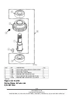
Page 192: ...s Southwestern Industries Inc ProtoTRAK SMX K2 K3 K4 Retrofit Safety Installation Maintenance Service and Parts List Manual Figure 123 K2 K3 Lower Vari Disc Drive P N 20778 5 assembly not available or...

Page 193: ...1 9 VS47 FRU K3 BRAKE SHOE 2 10 VS48 FRU K3 BRAKE SHOE PIVOT SLEEVE 1 11 VS17 FRU K3 SOCKET CAP SCREW M6 P1 0x35L 1 12 VS17 1 FRU K3 WASHER 6 1 13 VS17 2 FRU K3 NUT M6 P1 0 1 14 VS49 FRU K3 BRAKE SPRI...

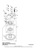
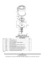
Page 194: ...7 TRAK Machine Tools Southwestern Industries Inc ProtoTRAK SMX K2 K3 K4 Retrofit Safety Installation Maintenance Service and Parts List Manual Figure 124 K2 K3 Upper Vari Disc Drive Sub Assy P N 20778...

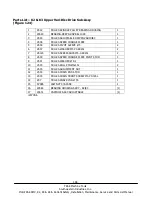
Page 195: ...RIVEN VARIDISC 1 4 VS36 FRU K3 SPEED CHANGE PLATE 1 5 VS38 FRU K3 PIVOT SLEEVE 5 2 6 VS37 FRU K3 WASHER M5 P0 8X20L 2 7 VS123 FRU K3 SCREW SHCS M5 0 8X20L 2 8 VS39 FRU K3 SPEED CHANGE PLATE PIVOT STUD...

Page 196: ...SHAFT 1 8 VS40 ROLL PIN 3x15L 2 9 VS24 COPPER BUSHING 2 10 VS24 1 WASHER WAVE 1 11 VS27 SPEED CHANGE HANDWHEEL 1 12 VS18 FULL DOG SOCKET SET SCREW M6 P1 0x10L 1 13 VS28 HANDLE 3 8 16NC 1 14 VS32 CHAI...

Page 197: ...P N Title Qty 1 VS110 FRU K3 MOTOR 3 HP 1 2 VS3 1 FRU K3 KEY 6x6x45L 1 3 VS2 FRU K3 STATIONARY MOTOR VARIDISC 1 4 VS6 FRU K3 BUSHING 1 5 VS5 FRU K3 ADJUSTABLE MOTOR VARIDISC ASSY 1 6 VS6 1 FRU K3 KEY...

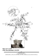
Page 198: ...191 TRAK Machine Tools Southwestern Industries Inc ProtoTRAK SMX K2 K3 K4 Retrofit Safety Installation Maintenance Service and Parts List Manual Figure 127 K2 K3 Lower Head Assembly P N 20779...

Page 199: ...1 16 K B67 FRU K3 CAP SCREW M6 P1 0x18L 4 17 K B29 FRU K3 CLUSTER GEAR KEY 3x3x45L 1 18 K B27 FRU K3 CLUSTER GEAR SHAFT UPPER BEARING 1 19 K B28 FRU K3 CLUSTER GEARS ASSEMBLY 1 20 K B94 FRU K3 SNAP R...

Page 200: ...DLE 1 60 KB 202 FRU K3 INDICATOR ROD 1 61 K B164 FRU K3 QUILL STOP MICRO SCREW 1 62 K B160 FRU K3 SNAP RING 16 1 63 K B124 2 FRU K3 FEED TRIP PLUNGER NUT M40 P0 7 2 64 K B124 1 FRU K3 FEED TRIP PLUNGE...

Page 201: ...NG PIN 3x3x10L 1 95 K B125 FRU K3 HANDWHEEL 1 96 K B111 FRU K3 REVERSE KNOB 1 97 K B100 FRU K3 CAP SET SCREW M5 P0 8x35L 1 98 25042 SCALE HEAD ROTATION R8 1 99 25043 POINTER SCALE 1 100 25044 DRIVE SC...

Page 202: ...ORM GEAR SHAFT SLEEVE 1 6 K B09 FRU K3 FEED DRIVE WORM GEAR SHAFT 1 7 K B11 FRU K3 KEY 3x3x25L 1 8 K B10 FRU K3 WORM SHAFT KEY 3x3x8L 1 9 K B03 FRU K3 FEED BEVEL PINION 1 10 K B02 FRU K3 BEVEL PINION...

Page 203: ...GEAR SHAFT CRANK 1 3 K B70 FRU K3 SHIFT CRANK 1 4 K B69 FRU K3 SPRING 3 x 20L 1 5 K B68 FRU K3 GEAR SHIFT PLUNGER 1 6 K B72 FRU K3 SHIFT KNOB 5 16 18NC 1 7 K B71 FRU K3 ROLL PIN 3 x 20L 1 8 K B63 FRU...

Page 204: ...tle UseAs Qty 1 K B166 QUILL PINION SHAFT EA 1 2 25706 BUSHING KIT PINION SHAFT R8 EA 1 3 K B91 WASHER EA 1 4 K B92 OVERLOAD CLUTCH WORM GEAR EA 1 5 K B93 OVERLOAD CLUTCH RING EA 1 6 K B92 1 SCREW SOC...

Page 205: ...K3 OVERLOAD CLUTCH SLEEVE 1 2 K B81 1 FRU K3 KEY 5x8x13L 1 3 K B80 FRU K3 OVERLOAD CLUTCH 1 4 K B79 FRU K3 SAFETY CLUTCH SPRING 1 5 K B78 FRU K3 OVERLOAD CLUTCH LOCKNUT 1 6 K B76 FRU K3 SOCKET SET SCR...

Page 206: ...WASHER 1 3 K B44 FRU K3 FEED WORM SHAFT BUSHING 1 4 K B43 FRU K3 WORM 1 5 K B59 FRU K3 PIN 3x12L 1 6 K B49 FRU K3 FEED REVERSE BEVEL GEAR 1 7 K B48 FRU K3 BUSHING 1 8 K B62 FRU K3 KEY 3x3x15L 1 9 K B...

Page 207: ...E DIRT SHIELD 1 3 20838 BEARING ANGULAR CONTACT U SET 2 7207 P4 1 4 K B136 BEARING SPACER SMALL 1 5 K B137 BEARING SPACER LARGE 1 7 K B133 NOSE PIECE 1 8 K B132 SLEEVE 1 9 K B131 BEARING DEEP GROVE 62...

Page 208: ...201 TRAK Machine Tools Southwestern Industries Inc ProtoTRAK SMX K2 K3 K4 Retrofit Safety Installation Maintenance Service and Parts List Manual Figure 134 K2 K3 Base Machine P N 20785...

Page 209: ...G BOLT 3REQ 3 16 C23 FRU K3 TABLE 42 OR 48 1 17 C31 FRU K3 STOP PIECE T BOLT 3REQ 3 18 C32 FRU K3 TABLE STOP PIECE 2REQ 2 19 C33 FRU K3 HEX NUT 3REQ 3 20 C37 FRU K3 TABLE LOCK BOLT HANDLE 1 21 C38 FRU...

Page 210: ...LED BALL BEARING 1 56 C80 FRU K3 BEARING RETAINER RING 1 57 C81 FRU K3 SOCKET HEAD CAP SCREW 1 58 C82 FRU K3 ELEVATING SCREW ASSEMBLY 1 59 C83 FRU K3 HANDLE 1 60 C84 FRU K3 ELEVATING CRANK 1 61 C85 FR...

Page 211: ...128 FRU K3 SCREW 1 91 C129 FRU K3 LOCKING BOLT 1 92 C130 FRU K3 RAM PINION SCREW 1 93 C131 FRU K3 RAM TURRET GIB 1 94 20851 FRU SK2 SK3 STOP PIECE T BOLT ASSY 1 95 20852 FRU SK2 SK3 TABLE LOCK HANDLE...

Page 212: ...205 TRAK Machine Tools Southwestern Industries Inc ProtoTRAK SMX K2 K3 K4 Retrofit Safety Installation Maintenance Service and Parts List Manual Figure 135 K4 Base Machine P N 20699...

Page 213: ...ble only in 20869 16 FC42 TABLE STOP BRACKET not shown on dwg 17 FC43 SADDLE TABLE GIB 18 FC44 SADDLE CHIP WIPER 19 FC45 SADDLE CHIP WIPER PLATE 20 FC46 TABLE LOCK PLUNGER 21 FC48 TABLE LOCK BOLT HAND...

Page 214: ...AP 62 FC93 KEY 63 FC94 ELAVATING SHAFT 64 FC95 GREASE SEALED BEARING 65 FC96 BEVEL PINION 66 FC97 SET SCREW 67 FC98 COLUMN BASE K4 68 FC102 SOCKET HEAD CAP SCREW 69 FC103 PEDESTAL 70 FC104 ELEVATING S...

Page 215: ...achine Tools Southwestern Industries Inc ProtoTRAK SMX K2 K3 K4 Retrofit Safety Installation Maintenance Service and Parts List Manual Figure 136 K2 K3 K4 Transformer Option 220V 440V P N 23470 220 or...

Page 216: ...chine Tools Southwestern Industries Inc ProtoTRAK SMX K2 K3 K4 Retrofit Safety Installation Maintenance Service and Parts List Manual Figure 137 K2 K3 K4 Transformer Options 220V 440V P N 23470 220 or...

Page 217: ...C MODIFIED 5 23440 220 ENCLOSURE ASSY TRANSFORMER OPTION 220V 5 23440 440 ENCLOSURE ASSY TRANSFORMER OPTION 440V 7 23454 3 CABLE ASSY SAFETY SWITCH XFMR MODULE DPM 8 5 16 18X1 2 25B SCREW SHCS STL BO...

Page 218: ...lieu of any other warranties express or implied including any implied warranty of merchantability or fitness for a particular purpose and of any other obligations or liability on the part of SWI or a...

Reviews: