58
TRAK Machine Tools
Southwestern Industries, Inc.
ProtoTRAK SMX, K2, K3 & K4 & Retrofit Safety, Installation, Maintenance, Service and Parts List Manual
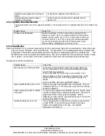
Potential Problem:
Check By:
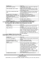
Bad ball screw
Visually inspecting the ball nut - if the nylon seal is broken or
deformed, if contamination has visibly entered the ball nut or if balls
are out of the ball nut, replace the ball screw.
Cranking the ball screw through a significant part of its travel. If it
jams, feels loose or has rough spots, replace the ball screw.
Using the dial indicator on a vertical flat of the ball screw to check for
backlash between the ball screw and ball nut.
Ball nut not tightened to
the yoke
Inspection for space between the head of the bolt and the ball nut i.e.
the retaining bolt has bottomed out in its thread and is not securing
the ball nut to the yoke properly.
Yoke loose in the saddle
Inspection for any motion of the yoke or looseness in the Yoke
mounting screws.
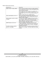
Oil lines sheared
Visual inspection.
Oil line blockage
Pump the oil and ensure that it flows evenly to the ways and ball
screw.
Ball screws not aligned
properly
Measure from the ball screw to the back of the saddle on both sides of
the yoke (the table must be removed). The measurements must be
within ±.005” end to end. See above explanations.
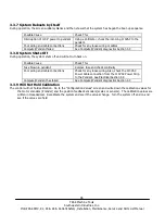
Note:
Ball screws are inspected throughout their entire travel for backlash and consistent torque. A ball screw should
be good for millions of inches of travel if installed properly. Do not be too quick to replace a ball screw if there is
insufficient indication that it is bad; this will just be a costly delay to resolving the real problem.
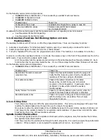
4.2.1 Keys to Ball Screw Alignment
X-axis
– there are 3 components that can cause misalignment: the yoke, the left side bearing
housing bracket, and the right side bearing housing.
Yoke
– the yoke is aligned at the factory and pinned in place. It is aligned to within +/-0.0005”
with a precise alignment tool. The yoke most likely is not causing the problem. If this were the
problem you would need to remove the pins and align the X ball screw with the back of the saddle.
Drill new holes and pin the yoke in place. The Y-axis ball screw bore is machined perpendicular to
the X bore. If the X-axis is aligned the Y-axis will also be aligned.
Left side table bearing housing
– this is most likely the cause of the misalignment. To align the
bracket and bearing housing, move them as close to the yoke as possible. Loosen the bracket bolts
and bearing housing bolts and then retighten. This should allow the bearing housing to align itself
up with the yoke.
Right side table bearing housing
– once again move the bearing housing as close to the yoke as
possible. Loosen the bearing housing and retighten. This should allow the bracket to align itself. If
you do not move the table toward the yoke the ball screw will tend to bend down slightly and cause
misalignment.
Y-axis
– the only component that can cause a misalignment problem is the motor mounting bracket.
To align this bracket, move the saddle as close to the front of the machine as possible. Loosen the
bracket and then retighten it. Once again moving the saddle forward allows the yoke to be as close
to the bearing housing as possible.
4.3
Computer/Pendant Diagnostics
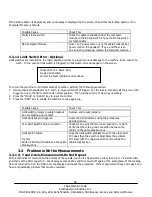
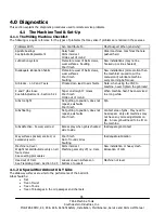
The pendant consists of 2 separate modules: the computer module, and LCD screen/enclosure.
In general, the pendant/computer module is best diagnosed by eliminating all other possible alternatives. The following
table lists some problems and what these problems can lead to.


