64
TRAK Machine Tools
Southwestern Industries, Inc.
ProtoTRAK SMX, K2, K3 & K4 & Retrofit Safety, Installation, Maintenance, Service and Parts List Manual
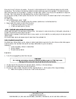
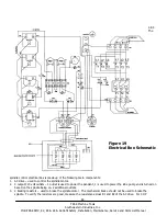
There are 4 fuses to check in the system. There are 2 in the pendant and 2 in the electrical cabinet, and one on the
breakout box. The top fuse in the electrical cabinet is 8 amps and fuses power to the pendant. The bottom fuse is 5
amps and fuses power to the auxiliary 1, auxiliary 2 and lube pump outlets. The 2 fuses in the pendant are 1 amp and
12 amps. The 12-amp fuses the cable breakout box, and the 1 amp the pendant.
If you have the auxiliary function option then there is 1 more fuse to check on the cable breakout box for the coolant or
mister option.
To check fuses:
1. Use a Volt/Ohmmeter; select “OHM”.
2.
Remove the fuse completely from the pendant, electrics box or cable breakout box.
3. Place a lead of the meter on each end of the fuse.
A good fuse reads 0 (zero) or close to it.
A bad fuse reads Open or Infinity.
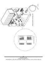
4.8.3 Cable Breakout Box Connections
This module is located on the back side of the machine. It consists of 3 motor connections, 3 limit switch connections, 3
encoder connections and an E-stop connection.
Machines with an auxiliary function option have 2 more outlets. A 110 V outlet for a coolant pump or air solenoid and an
indexer outlet.
The coolant pump signal and indexer signal comes down from umbilical #2.
4.8.4 Cable Connections
The TRAK knee mill machines use 10+ cables to communicate between systems. It is often the case that what appears
to be the failure of an electrical component is actually attributable to a poor connection.
Indications:
Control problems, chronic or intermittent.
Motor problems
Measurement problems.
Explanation:
1.
Turn off and
unplug
the system from the wall.
CAUTION!
Do not plug and unplug connectors with the system power on. This may cause
damage to the connector board and harm to the technician.
2.
Visually inspect the connections for excessive debris, moisture, or obvious damage.
3.
Carefully clean any chips away from the connectors.
4.
One-by-one, take out each connector and then plug them back in. Do the same at the computer/display.
5. Make sure to tighten up the screws on each of the connectors.

