79
TRAK Machine Tools
Southwestern Industries, Inc.
ProtoTRAK SMX, K2, K3 & K4 & Retrofit Safety, Installation, Maintenance, Service and Parts List Manual
5.1.5 Cable Routing on Machine
Whenever you replace a cable or reroute a cable it is very important to keep the power cables and logic cables
separated from each other. The power cables consist of the (3) 110-volt motor cables and (2) 110-volt power
cables for the pendant, and a coolant pump or solenoid power cable. The logic cables are used to carry encoder
signals between the cable breakout box and computer module. Mixing of the power and logic cables may cause
noise from the power cables to interrupt the signals in the logic cables. This can lead to intermittent axis faults or
repeatability problems. See Figure 15 and 16 for a layout of the cable connections.
5.1.6 TRAK Sensor
5.1.6.1 Replacing the M5 Base
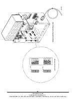
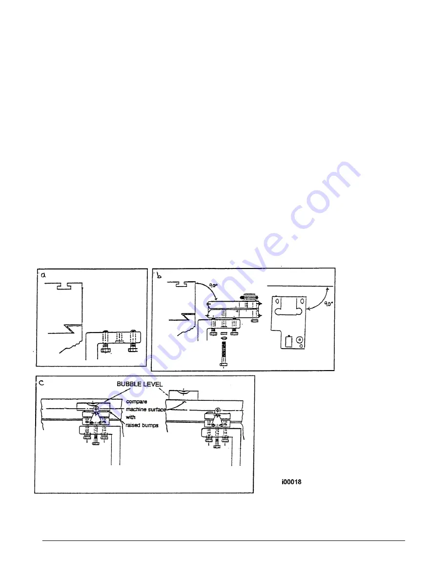
See Figures 25 and 26.
1.
Remove the sensor by removing the clamp screw and then backing the load screw out a few turns.
The sensor should lift off the base easily.
2.
Remove the old M5 Base by removing the two 1/4-20 hex head screws that are threaded into the
base.
3.
Assemble the new base as per Figure 25.
4.
Use a bubble level to align the raised bumps on the base with the table for X axis or saddle ways for
Y-axis.
5.
A dial indicator may be used to align the bumps on the base instead of a bubble level.
Figure 25
M5 Base Mounting

