9
TRAK Machine Tools
Southwestern Industries, Inc.
ProtoTRAK SMX, K2, K3 & K4 & Retrofit Safety, Installation, Maintenance, Service and Parts List Manual
2.4 Installation Instructions & Checklist
Installer: Use this checklist to assure a complete set-up of the K2, K3, K4 or SMX 2 or 3-axis retrofit.
1.
Shut off power to the machine.
2.
Visually inspect the 220 or 440V wiring going into the electrical panel. Visually verify the
wiring is correct per our wiring diagram. Make sure a strain relief is being used where the
wiring enters the cabinet. Have the customer repair any wiring discrepancies. Measure the
220 volt and 110 volt input power to make sure it is within specification. If not, notify
customer and report on service report.
3.
Clean the machine if needed and remove any remaining grease.
4.
Unlock the table, saddle, and knee gib locks.
5.
Mount the pendant to the pendant arm using (4) 1/4-20 x 3/4" socket head cap screws.
6.
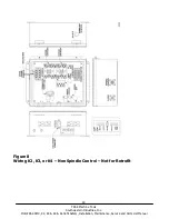
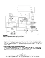
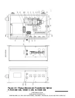
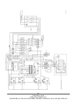
Make and check all the proper electrical connections from the pendant to the electric box.
See the pendant and electric box wiring diagrams.
7.
On retrofits, place the nameplate serial # plate (21934) on the pendant arm. This serial #
plate is the main system # for that machine. Place the serial # plate using 2 drive screws to
the front of the pendant arm near the pivot point of the arm. Use a #36 drill bit for drive
screws. See figure 57.
8.
On retrofits and TRAK knee mills make sure to plug in the machine ID key on the top corner
of pendant before powering up the pendant. Failure to do so may cause an improper
configuration file. If this happens, go to service code 313 and load the defaults. Loading
defaults will erase any calibration factors that have been done. See pendant connection –
Figure 13.
9.
Turn on the power to the machine and to the pendant.
10.
Load master and slave software from software upgrade disk or USB. The pendant may or may
not have the latest software loaded. (Retrofits only.)
11.
Lubricate all the way surfaces and the ball screws.
12.
Jog the table and saddle back and forth until the way surfaces are well lubricated. Oil should
be visible on all the way surfaces.
13.
Check the level of the machine. The machine should be level to within 0.0005" front to back
and 0.0005" side to side. Even though it is the responsibility of the customer, make any
adjustments if necessary.
14.
Check tram on head and adjust as necessary.
15.
Check to make sure that the E-Stop button is functioning correctly. N/A to retrofits for
spindle.
16.
Perform Service Code 12, Feed Forward Constant.
17.
Perform Service Code 11 to automatically calculate the backlash for the X and Y-axis of glass
scale machines
18.
Perform Service Code 123 to calibrate the X and Y-axis using a 150mm standard.
19.
Perform Service Code 127 and 128 to manually calculate the backlash for the X and Y-axis of
single feedback machines (i.e. motor encoder only).
20.
Check for positional accuracy and repeatability on the X and Y-axis using programs XREPEAT
2 AXIS.PT4 and YREPEAT 2 AXIS.PT4 respectively. Positioning and repeatability values
should be less than or = to 0.0005”. Programs can be found on C drive under the PT4SX
folder followed by the SWI TEST PROGRAMS folder.
21.
For 2 axis machines - perform Service Code 123 and press QUILL softkey to calibrate the Z-
axis quill using a 75mm or 3” standard.
22.
For 3 axis machines - perform Service Code 123 and press Z softkey to calibrate the Z-axis
ball screw encoder using a 75mm or 3” standard.
23.
Perform Service Code 100 in both directions for the X, Y, and Z-axis to verify that the feed
rate shown on the display is at least 120 ipm.
24.
Run the spindle at various speeds in both high and low gear for 15 minutes. Verify head


