19
English
EQUIPMENT ASSEMBLY
Assembly of the Lower Arm
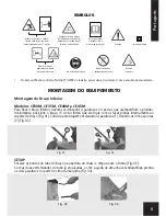
Models CE30M, CE35M, CE40M and CE45M
To fasten the lower arm, use 4 screws and 4 nuts that are provided with the product. At first, position the arm
(1) so that the flat surfaces remain inside the arm bracket [Fig. 01, Pag. 06]. Complete the assembly inserting the
screws (1), fastening them with the nuts (2), [Fig. 02, Pag. 06].
Model CE30P
Simultaneously place the two ends of the lower arm on brace, fitting it into the holes on chassis and pushing until
it seats completely. [Fig. 03, Pag. 06] . With both ends of the tube fitted use a Phillips screwdriver to attach to the
upper part of the engine [Fig. 04, Pag. 06].
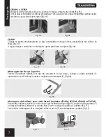
Models CE30P2 and CE35P
Simultaneously place the two ends of the lower arm on brace, fitting it into the holes on chassis and pushing until
it seats completely. [Fig. 05, Pag. 07] . With both ends of the tube fitted use a Phillips screwdriver to attach at the
side of the engine [Fig. 06, Pag. 07].
Model CE40P
Simultaneously place the two ends of the lower arm on brace, fitting it into the holes on chassis and pushing until it seats
completely. [Fig. 07, Pag. 07]. Then place the fastening plate on brace - with protruding side facing down - seating it
in the hole so that it no longer moves. Then place the knob and tighten the assembly [Fig. 08, Pag. 07].
Assembly of the Upper Arm
Insert the screws making them cross the two arms. Put the wavy washer (1), adjusting it the arm profile and
tighten the set with the handle retaining nut (2), [Fig. 09, Pag. 07].
Assembling of Baffle for Lateral Outlet for Grass (models CE30M, CE35M, CE40M and CE45M)
To assemble the baffle, position it on the chassis as shown in the figure [Fig. 10, Pag. 07], fit the two M6 (1) screws
into the baffle holes, using the flat washers (2) between the screw head and the baffle [Fig. 11, Pag. 07].
To complete the assembly and fasten the assembly using the nuts M6 (3) that accompany the product [Fig. 11, Pag. 07].
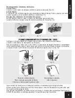
Catcher Assembly
Bag Catcher
Connect the grass bag to the grass bag frame the same way as you have done to the part that has already
been fitted [Fig. 14, Pag. 08].
Rigid Catcher
It is necessary to join the upper half to lower half. After joining, do not try to separate them, as this may
damage the catcher [Fig. 15, Pag. 08].
Placing the catcher on the mower
Both types of catchers [bag and rigid] are attached in the same manner: Raise the deflector and attach the
catcher to chassis [Fig. 16, Pag. 08].
OPERATION AND FORM OF USAGE
Check whether the mower electric tension is the same as the electric mains.
Plug the cord in the switch and cord attach.
For your safety and to prevent the cord from getting unplugged while the work is being done, bend the cable and
run it through the cable attach hole and fit it to the catch; only then connect the cord to the mower plug [Fig. 17,
Pag. 08], [Fig. 18, Pag. 08].
Press the yellow button [Fig. 19]. Pull the lever towards the arm. Once that is done the yellow button can

