background image

Page  13

TEF 4600 CONTROL SYSTEM  - 

INSTALLATION AND USER MANUAL
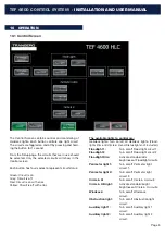
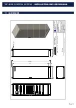
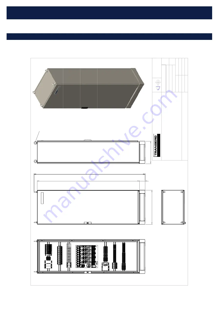
11   GA DRAWING

 1800 

 100 

 600 

 1955,6 

 400 

Lifing lugs

THE INFORMATION CONTAINED IN THIS DRAWING IS THE SOLE PROPERTY 

OF TRANBERG AS. ANY REPRODUCTION IN

PART OR AS A WHOLE WITHOUT THE WRITTEN PERMISSION OF TRANBERG A

S IS PROHIBITED. TRANBERG AS 

GA Drawing

Rittal Enclosure for TEF 4600 Control System

460A112642

Drw. no.

460A112642

15.06.2017

Unless otherwise specified: Dimensions are in mm. Tolerances according to  ISO 2768-M

Projection

1   of   1

1:10

A3

Format

Rev.

Appr.

Contr.

Cust.

Approvals

Design

CKR

Date

Scale

Page

Subst. by

Subst. for

File 

Strandsvingen 6, P.O.Box 8033 N-4068 STAVANGER, NORWAY www.tranberg.com  info@tranberg.com

Summary of Contents for TEF 4600

Page 1: ...of this document may be copied or reproduced in any form or by any means and the information contained within it is not to be communicated to a third party without the prior written consent of Tranberg AS The document or any part of it may not be translated to any other language without the written approval from Tranberg AS DISCLAIMER Tranberg AS endeavors to ensure that all informa tion in this d...

Page 2: ...ite Control 4 8 COMMISSIONING 4 9 DISPOSAL 4 10 OPERATION 5 10 1 Control Screen 5 10 2 Status Light Screen 6 10 2 1 Suppress 6 10 2 2 Activate Manual activation 7 10 2 3 Dim 7 10 2 4 Activation Timeout 7 10 2 5 Dim Timeout 7 10 2 6 Inspection Interval 7 10 2 7 Status light Fault indicators 7 10 3 Setup screen page 1 8 10 3 1 Activate Modbus TCP 8 10 3 2 Choose language 8 10 3 Setup screen page 2 9...

Page 3: ... blocks It s possible to connect several remote control panels as well as connect the sys tem to a remote SCADA system Connect SCADA system to the general alarm output NO NC volt free contact to retrieve instant notification in case anything should fail 6 TERMINAL CONNECTIONS Terminal connections overview X1 230 VAC Supply X2 Helideck light 230V Outputs X3 24VDC Remote Signals X4 External alarm In...

Page 4: ...ance at installa tions with high levels of background lighting without risk ing glare at less well lit installations To adjust light level replace resistor plugs in accordance with table below 7 2 2 On site Control Once installed and with reference to the Installation Man ual TUM6332 make sure that the system functionality is as per the Installation Manual and specifications Check the local on off...

Page 5: ...s off with error The available lights to control are Helideck lights Turn on off all Helideck lights Flood lights Dim and Circle H and Status lights not included Floodlight 1 Turn on off Flood light circuit 1 Floodlight 2 Turn on off Flood light circuit 2 Floodlight Dim Activate standard dim brightness of Floodlight circuits Perimeter light 1 Turn on off Perimeter light circuit 1 Perimeter light 2...

Page 6: ...suppressed the Status lights will not activate by manual activation nor external Fire Gas signal Dim function is also disabled in this mode Activate and Dim are reset when Suppress mode is ac tivated External Fire Gas signal is suppressed until Suppress mode is deactivated When Suppress mode is activated the following indica tion lights will blink at 1Hz interval Activate button Dim Button Main Li...

Page 7: ...up screen 10 2 5 Dim Timeout Dim timeout will deactivate the dimming function when the timer has elapsed Default value is 30 minutes The Dim timeout is enabled in the Setup screen 10 2 6 Inspection Interval Inspection interval is a time span of days which when counted down will trigger an Inspection Required indi cator in the Status Light screen The Operator can man ually enter the number of days ...

Page 8: ... Modbus TCP If Modbus TCP is used for control and monitoring with external control system this function is activated here For new connection disable Modbus enter IP address of Client and finally enable Modbus again 10 3 2 Choose language These are the languages which can be chosen for this application ...

Page 9: ...nable disable the internal buzzer of the HMI touch panel When enabled the buzzer will acti vate when an alarm is present 10 3 4 Helideck Lights Timeout Helideck Lights Timeout will deactivate the All Helideck Lights On function when the timer has elapsed The Button will be green when Enabled 10 3 Setup screen page 2 ...

Page 10: ...el must use the Take Control button to control the Helideck lights When not in control a panel will only be able to monitor the status of the Helideck lights If the remote panel does not have control and an attempt is made to turn on a light circuit Take Control button will display the following text Local panel has control 10 3 6 Panel is local Enable this if the Panel is local 10 3 7 Panel is re...

Page 11: ...tion All Helidecks Lights on This setup page dictates which light circuits are enabled for the function All Helideck Lights On F ex if Flood lights are to be exempt from the All helideck lights on function one simply has to disable Flood lights with the Enable button 10 3 Setup screen page 4 ...

Page 12: ...ion of Alarms that are currently active or acknowledged An Alarm will blink when raised and unacknowledged Ack Sel will acknowledge selected alarm Ack All will acknowledge all alarms in list Reset Sel will remove selected acknowledged alarms from the list Reset All will remove all acknowledged alarms from the list ...

Page 13: ... WRITTEN PERMISSION OF TRANBERG AS IS PROHIBITED TRANBERG AS GA Drawing Rittal Enclosure for TEF 4600 Control System 460A112642 Drw no 460A112642 15 06 2017 Unless otherwise specified Dimensions are in mm Tolerances according to ISO 2768 M Projection 1 of 1 1 10 A3 Format Rev Appr Contr Cust Approvals Design CKR Date Scale Page Subst by Subst for File Strandsvingen 6 P O Box 8033 N 4068 STAVANGER ...

Page 14: ...ON AND USER MANUAL R Stahl Tranberg AS E info stahl tranberg com stahl tranberg com Main office Strandsvingen 6 N 4032 Stavanger Norway T 47 51 57 89 00 F 47 51 57 89 50 Office Oslo Luhrtoppen 2 N 1470 Lørenskog Norway T 47 24 08 44 10 ...

Reviews: