Page 3
TEF 4600 CONTROL SYSTEM -
INSTALLATION AND USER MANUAL
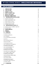
1. INTRODUCTION
Thank you for purchasing this product!
For installation, maintenance and assurance of a long
life of this product, please follow this manual.
For more detailed mounting instructions on the Rittal en-
closure please see user manual TUM5915.
For more detailed mounting instructions on the Rittal
Sockel-System-Flex please see user manual TUM5916.
2. APPLICATIONS
Control system for Tranberg TEF 4600 Helideck Light
Control.
Status lights:
Up to 2 main lights and 2 repeater lights.
Floodlights:
Up to 2 Floodlight circuits.
Perimeter lights:
Up to 2 Perimeter lights circuits.
Obstruction light:
One Obstruction light circuit.
Windsock:
One Windsock circuit.
Circle & H:
One Circle & H circuit.
Auxiliary:
Two Auxiliary light circuits.
3 CONTENT IN BOX
•
1 pc control cabinet
•
1 Pack of Resistors for configuration of C&H
•
Flex-Block Trim Panels
4 SAFETY PRECAUTIONS
Note that changes made to the product and/or instal-
lation of components which do not conform to the ap-
proval, may be a safety violation. The manufacturer will
in no circumstance be held responsible for such activity.
For your health and safety, always use safety gear suited
for the task. Be certain to follow codes, regulations and/
or specific procedures that are related to the installation.
The TEF 4600 control cabinet shall be stored in a dry
place. Storage temperature range (non-condensing):
-10°C to +55°C
5 ABOUT THE SYSTEM
The standard control system consists of a control cabinet
with power supply, PLC, circuit breakers, terminal blocks.
It’s possible to connect several remote control panels as
well as connect the sys¬tem to a remote SCADA-system.
Connect SCADA system to the general alarm output NO/
NC volt free contact to retrieve instant notification in case
anything should fail.
6 TERMINAL CONNECTIONS
Terminal connections overview
-X1: 230 VAC Supply
-X2: Helideck light 230V Outputs
-X3: 24VDC Remote Signals
-X4: External alarm Interface
-X5: Status Lights
-X6: C&H Lights
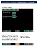
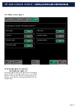
7.1 CONFIGURATION STATUS LIGHTS
7.1.1 Enable Installed Lights
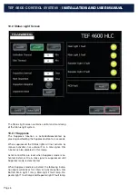
The left side has enable function for each Helideck light
module. The Helideck light modules that are present on a
given vessel or installation shall be set to Enable for con-
trol and monitoring of said light. The Button will be green
when Enabled.
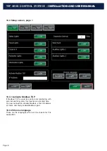
7.1.2 Status Light Automatic Test:
This Function will enable or disable Automatic test of
the Status Lights. When enabled the Status Lights will
perform a self check once per 24 hours. The test is per-
formed by the lamps being turned on for 1 second at very
low light intensity. This test will serve as a early warning
diagnostics. If alarm is present the lamp will report this to
the Control System and an Alarm with descriptive text will
be shown in the Alarms screen.
7.1.3 Status Light On Timeout
Activation timeout will deactivate the Status light system
when the timer has elapsed. Default value is 30 minutes.
The Button will be green when Enabled.
7.1.4 Status Light Dim Timeout
Dim timeout will deactivate the dimming function when
the timer has elapsed. Default value is 30 minutes. The
Button will be green when Enabled.
7.1.5 Helideck Lights Timeout
Helideck Lights Timeout will deactivate the «All Helideck
Lights On» function when the timer has elapsed. The But-
ton will be green when Enabled.


