The condenser and subcooler consist of 7mm in-
ner-grooved copper tube which contain the refrigerant,
large
fi
ns are in the air
fl
ow side and fans that draw air
through the
fi
ns and tubes. Heat is transferred from the
refrigerant through the tubes and
fi
ns to the air. High
pressure gas from the compressor enters the tubes of
the condenser through a distribution header (state 2b).
As refrigerant
fl
ows through the tubes, the heat of com-
pression and cooling load are rejected to the air. In this
process the refrigerant is de-superheated, condensed
(states 2b to 3) and
fi
nally subcooled (states 3 to 3b) to a
temperature slightly above the ambient air temperature.
The subcooled liquid refrigerant is collected in the leav-
ing header where it is transferred to the liquid line (state
3b).
The air
fl
ow rate of fan is controlled according to princi-
ple of getting maximum ef
fi
ciency, mean while consid-
ering the system pressure differential. If a warm enough
ambient is sensed, all the fans will run. If the ambient is
cooler, some fans are shut off. Fan staging depends on
the chiller load, evaporator pressure, condenser effec-
tiveness, ambient temperature, and numbers and sizes
of fans installed on the circuit.
RTAG evaporator is CHIL evaporator which is patented
by Trane. It is divided into two area: high ef
fi
ciency boil
area and high oil concentration area. A distributor is in-
stalled in bottom of high ef
fi
ciency boil area. Two phase
refrigerant (state 4) inject towards to heat exchange
through the distributor. The uplifted bubbles enforce the
disturb of refrigerant, so the heat exchange ef
fi
ciency
is high. The liquid refrigerant-oil mixture continue
fl
ow
to high oil concentration area and go on evaporating,
oil concentration further increase, and
fi
nally go back
to compressor. Refrigerant vapor exits the evaporator
through the suction line (state 1).
The material of evaporator shell is carbon steel, and
tube is internally and externally
fi
nned seamless cop-
motor terminal
Discharge
check valve Female rotor
Step load
valve
Oil check valve
(internal)
Interior o
il fil
ter
Male rotor
Male rotor unload piston
motor rotor
ter
screen
Auxiliary Inlet Port
Operating Principies
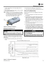
Figure 62. Compressor inner configuration
Figure 63. Compressor with Auxiliary Inlet Port
98
RTAG-SVX001H-EN


