background image

4

TK 56117-6-OP-EN

S

Sa

affe

etty

y P

Prre

ecca

au

uttiio

on

nss .. .. .. .. .. .. .. .. .. .. .. .. .. .. .. .. .. .. .. .. .. .. .. .. .. .. .. .. .. .. .. .. .. .. .. .. .. .. .. .. .. .. 6

6

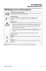
Danger, Warning, Caution, and Notice . . . . . . . . . . . . . . . . . . . . . . . . 6

Safety Decals . . . . . . . . . . . . . . . . . . . . . . . . . . . . . . . . . . . . . . . . . . . 6

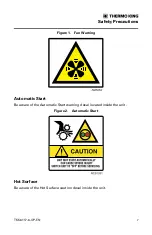
Blower Fan . . . . . . . . . . . . . . . . . . . . . . . . . . . . . . . . . . . . . . . . . . . . 6
Automatic Start . . . . . . . . . . . . . . . . . . . . . . . . . . . . . . . . . . . . . . . . 7
Hot Surface . . . . . . . . . . . . . . . . . . . . . . . . . . . . . . . . . . . . . . . . . . . . 7
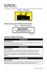
California Proposition 65 Warning Nameplate . . . . . . . . . . . . . . . 8

General Safety Practices . . . . . . . . . . . . . . . . . . . . . . . . . . . . . . . . . . . . 8

U

Un

niitt D

De

essccrriip

pttiio

on

n.. .. .. .. .. .. .. .. .. .. .. .. .. .. .. .. .. .. .. .. .. .. .. .. .. .. .. .. .. .. .. .. .. .. .. .. .. .. .. .. .. .. .. .. .. 9

9

Unit Overview . . . . . . . . . . . . . . . . . . . . . . . . . . . . . . . . . . . . . . . . . . . . . . 9

Engine . . . . . . . . . . . . . . . . . . . . . . . . . . . . . . . . . . . . . . . . . . . . . . . . . . . . 11

HMI Controller. . . . . . . . . . . . . . . . . . . . . . . . . . . . . . . . . . . . . . . . . . . . . 12

Protection Devices . . . . . . . . . . . . . . . . . . . . . . . . . . . . . . . . . . . . . . . . . 12

M

Ma

an

nu

ua

all P

Prre

ettrriip

p IIn

nssp

pe

eccttiio

on

n .. .. .. .. .. .. .. .. .. .. .. .. .. .. .. .. .. .. .. .. .. .. .. .. .. .. .. .. .. .. .. .. .. 1

13

3

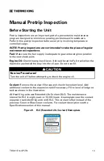
Before Starting the Unit . . . . . . . . . . . . . . . . . . . . . . . . . . . . . . . . . . . . 13

O

Op

pe

erra

attiin

ng

g IIn

nssttrru

uccttiio

on

nss .. .. .. .. .. .. .. .. .. .. .. .. .. .. .. .. .. .. .. .. .. .. .. .. .. .. .. .. .. .. .. .. .. .. .. .. .. 1

17

7

HMI Display Icons . . . . . . . . . . . . . . . . . . . . . . . . . . . . . . . . . . . . . . . . . 18

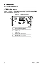
HMI Display Icons and Descriptions . . . . . . . . . . . . . . . . . . . . . . . . . 19

HMI Display Keys and Descriptions. . . . . . . . . . . . . . . . . . . . . . . . . . 20

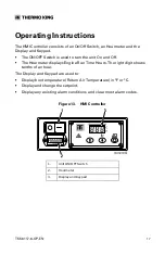
Turning the Unit OFF and OFF . . . . . . . . . . . . . . . . . . . . . . . . . . . . . . 21

Standard Display . . . . . . . . . . . . . . . . . . . . . . . . . . . . . . . . . . . . . . . . . . 21

Changing the Setpoint . . . . . . . . . . . . . . . . . . . . . . . . . . . . . . . . . . . . . 22

Starting the Diesel Engine . . . . . . . . . . . . . . . . . . . . . . . . . . . . . . . . . . 24

Alarms. . . . . . . . . . . . . . . . . . . . . . . . . . . . . . . . . . . . . . . . . . . . . . . . . . . . 25

Alarm Code Types . . . . . . . . . . . . . . . . . . . . . . . . . . . . . . . . . . . . . 25
Alarm Code Notification . . . . . . . . . . . . . . . . . . . . . . . . . . . . . . . . 25

Table of Contents

Summary of Contents for Thermo King Heat King HK450

Page 1: ...Revision B November 2019 T TK K 5 56 61 11 17 7 6 6 O OP P E EN N Heat King HK450 HO and HK450 MAX Operator s Manual ...

Page 2: ...n nd da at ti io on ns s o or r d de es sc cr ri ip pt ti io on ns s c co on nt ta ai in ne ed d h he er re ei in n T Th he e p pr ro oc ce ed du ur re es s d de es sc cr ri ib be ed d h he er re ei in n s sh ho ou ul ld d o on nl ly y b be e u un nd de er rt ta ak ke en n b by y s su ui it ta ab bl ly y q qu ua al li if fi ie ed d p pe er rs so on nn ne el l F Fa ai il lu ur re e t to o i im mp p...

Page 3: ...r manuals The survey is accessible through any internet connected device with a web browser Scan the Quick Response QR code or click or type the web address https tranetechnologies iad1 qualtrics com jfe form SV_2octfSHoUJxsk6x Q_ CHL qr Q_JFE qdg to complete the survey I In nt tr ro od du uc ct ti io on n ...

Page 4: ...w 9 Engine 11 HMI Controller 12 Protection Devices 12 M Ma an nu ua al l P Pr re et tr ri ip p I In ns sp pe ec ct ti io on n 1 13 3 Before Starting the Unit 13 O Op pe er ra at ti in ng g I In ns st tr ru uc ct ti io on ns s 1 17 7 HMI Display Icons 18 HMI Display Icons and Descriptions 19 HMI Display Keys and Descriptions 20 Turning the Unit OFF and OFF 21 Standard Display 21 Changing the Setpoi...

Page 5: ...s 32 Belt Tension 33 Unit Controller 33 Electrical Control System 33 Electrical Fuses 34 S Se er ri ia al l N Nu um mb be er r L Lo oc ca at ti io on ns s 3 35 5 M Ma ai in nt te en na an nc ce e I In ns sp pe ec ct ti io on n S Sc ch he ed du ul le e 3 37 7 W Wa ar rr ra an nt ty y 3 39 9 EPA and ARB Supplemental Emissions Warranty Statement 39 T Tr ro ou ub bl le es sh ho oo ot ti in ng g 4 40 0...

Page 6: ... le e Indicates an imminently hazardous situation which if not avoided will result in death or serious injury W WA AR RN NI IN NG G E Ex xa am mp pl le e Indicates a potentially hazardous situation which if not avoided could result in death or serious injury C CA AU UT TI IO ON N E Ex xa am mp pl le e Indicates a potentially hazardous situation which if not avoided could result in minor or moderat...

Page 7: ...ing Automatic Start Be aware of the Automatic Start warning decal located inside the unit Figure 2 Automatic Start Hot Surface Be aware of the Hot Surface caution decal inside the unit S Sa af fe et ty y P Pr re ec ca au ut ti io on ns s ...

Page 8: ... In nj ju ur ry y Do not apply heat to a closed cooling system Before applying heat to a cooling system drain it Then flush it with water and drain the water Antifreeze contains water and ethylene glycol The ethylene glycol is flammable and can ignite if the antifreeze is heated enough to boil off the water C CA AU UT TI IO ON N S Sh ha ar rp p E Ed dg ge es s Exposed coil fins can cause laceratio...

Page 9: ...ing models HK450 HO High Output 36 000 BTU HK450 MAX 50 000 BTU H HK K4 45 50 0 H HO O heat the cargo area by routing heated engine coolant through the radiator coil A blower in front of the coil transfers the heated air into the cargo box H HK K4 45 50 0 M MA AX X provides additional heating capacity by incorporating an exhaust system heat exchanger Engine coolant is routed through the heat excha...

Page 10: ...p 4 Engine Thermostat 5 Exhaust Muffler Heat Exchanger HK450 MAX units only Exhaust Muffler not shown HK450 HO units only 6 Alternator 7 Battery Box and Hold Down Bracket 8 Maintenance On Off Switch 9 Oil Drain Plug 10 Oil Filter 11 Oil Level Dipstick 12 Air Filter U Un ni it t D De es sc cr ri ip pt ti io on n ...

Page 11: ...s 1 Air Inlet 2 Air Outlet Engine A Thermo King TK 270VF indirect injected two cylinder water cooled diesel engine powers the unit Refer to the Specifications section of this manual for more information U Un ni it t D De es sc cr ri ip pt ti io on n ...

Page 12: ... sensor signals the TG VII Base Controller to shut down the unit if the engine coolant temperature exceeds the specified limit C Co oo ol la an nt t L Le ev ve el l S Sw wi it tc ch h This switch monitors the coolant level If coolant level becomes low an alarm code is displayed on the HMI Controller E En ng gi in ne e L Lo ow w O Oi il l P Pr re es ss su ur re e S Sw wi it tc ch h This switch sign...

Page 13: ...g gi in ne e O Oi il l Check the engine oil level It should be at the Full mark when the dipstick is pushed all the way into the oil pan Do not overfill C CA AU UT TI IO ON N S Se er rv vi ic ce e P Pr ro oc ce ed du ur re es s Turn the unit off before attempting to check the engine oil C Co oo ol la an nt t Remove the coolant filler cap and check the coolant level Add additional coolant to the ex...

Page 14: ...olants dilute interact with the additive packages of extended life coolant which significantly reduces the service life of the coolant N No ot te e The use of 55 45 pre mixed ELC is recommended to ensure that deionized water is being used If 100 full strength concentrate is used deionized or distilled water is recommended instead of tap water to ensure the integrity of the cooling system is mainta...

Page 15: ... 15 Figure 11 Coolant Expansion Tank and Filler Cap RCS1162 1 2 1 Coolant Expansion Tank Pressure Cap 2 Coolant Filler Cap check add coolant here M Ma an nu ua al l P Pr re et tr ri ip p I In ns sp pe ec ct ti io on n ...

Page 16: ...Do oo or rs s Make sure that the doors and weather seals are in good condition The doors should latch securely and the weather seals should fit tightly E El le ec ct tr ri ic ca al l Check all electrical connections to make certain they are securely fastened Wires and terminals should be free of corrosion cracks and moisture L Le ea ak ks s Inspect for fuel leaks engine oil leaks and coolant leaks...

Page 17: ... unit On and Off The Hourmeter displays Engine Run Time Hours The right digit shows tenths of an hour The Display and Keypad are used to Display box temperature Return Air Temperature in F or C Display and change the setpoint Display any existing alarm conditions and clear most alarm codes Figure 13 HMI Controller 1 Unit ON OFF Switch 2 Hourmeter 3 Display and Keypad ...

Page 18: ...t temperature box temperature and alarm information to the operator Figure 14 HMI Display Icons 1 Return Air Temperature Icon 2 Setpoint Icon 3 Alarm Icon 4 Red C Centigrade Display 5 Blue F Fahrenheit Display O Op pe er ra at ti in ng g I In ns st tr ru uc ct ti io on ns s ...

Page 19: ...or 30 seconds and then turns off one or more Log Alarms have occurred If the Alarm Icon is on steady yellow and does not turn off one or more Check Alarms have occurred If the Alarm Icon is flashing red then one or more Shutdown Alarms have occurred and the unit has been shut down Immediate action must be taken Consult the Alarm Codes table at the back of this section for suggested corrective acti...

Page 20: ...de is shown on the display pressing and holding the SELECT Key will clear that alarm code Each alarm code must be cleared individually 2 UP ARROW Key Setpoint When the setpoint is shown on the display pressing the UP ARROW Key will increase the setpoint Alarms When an alarm code is shown on the display and more than one alarm code exists pressing the UP ARROW Key will scroll forward through the ex...

Page 21: ...en the unit is ready to run the Standard Display is shown This is the default display that appears if no other display function is selected The Standard Display shows the box temperature as indicated by the Return Air Temperature Icon located above the Select Key The box temperature shown here is 33 F 1 C and the hourmeter shows that the unit s diesel engine has run for a total of 18 6 hours Figur...

Page 22: ...be shown on the display 1 SELECT Key 2 SETPOINT Icon When the current setpoint is shown on the display press the UP ARROW Key and or DOWN ARROW Key as necessary to chose the new setpoint Here the setpoint has been increased to 40 F 4 C using the UP ARROW Key The factory established minimum setpoint temperature is 20 F 29 C and the maximum is 80 F 27 C Figure 18 UP ARROW Key 1 UP ARROW Key 2 SELECT...

Page 23: ...n to the original setpoint After the new setpoint has been confirmed by pressing the SELECT Key the display will return to the Standard Display The Return Air Temperature Icon located above the Select Key will appear and the box temperature will be shown in the display Figure 19 Return Air Temperature Icon 1 Return Air Temperature Icon I Im mp po or rt ta an nt t Always check to be sure the desire...

Page 24: ... I In nj ju ur ry y The unit may start automatically without warning if the Engine On Off Switch is in the On position N NO OT TI IC CE E E Eq qu ui ip pm me en nt t D Da am ma ag ge e Never use starting fluid Damage to the engine can occur Figure 20 Standard Display When the engine is preparing to start the HMI Controller will continue to show the Standard Display The preheat buzzer located on th...

Page 25: ...n is corrected and cleared S Sh hu ut td do ow wn n A Al la ar rm ms s This level of alarm serves as a notice that continued operation could cause damage to the unit or the load The unit will be shut down to protect the unit and load If Shutdown Alarm s are present the Alarm Icon will flash in red on the display and will remain on until the alarm condition is corrected and cleared The unit will be...

Page 26: ...en only the Alarm Icon is present the most recent alarm code will be shown on the display Figure 22 Display Alarm Codes 1 Alarm Icon 2 SELECT Key If more than one alarm code has been set they are displayed with the most recent alarm shown first Use the UP ARROW Key and or DOWN ARROW Key to scroll through the alarms O Op pe er ra at ti in ng g I In ns st tr ru uc ct ti io on ns s ...

Page 27: ...he alarm code currently being displayed Continue to press and hold the SELECT Key as necessary to clear any remaining alarms When all alarms have been cleared the display will show all dashes to indicate that no alarm codes exist The Standard Display will reappear in about 10 seconds Figure 24 Clearing Alarm Codes 1 SELECT Key 2 All Dashes O Op pe er ra at ti in ng g I In ns st tr ru uc ct ti io o...

Page 28: ...t end of the day 07 Check Engine RPM Sensor Report alarm at end of the day 11 Unit Controlling on Alternate Sensor Manually monitor load temperature Report alarm at end of the day 12 Sensor Shutdown Both Return Air Temperature and Discharge Air Temperature sensors have failed and unit is shut down Repair immediately 13 Sensor Check Manually monitor load temperature Report alarm at end of the day 1...

Page 29: ...eed Report alarm at end of the day 61 Low Battery Voltage If unit is shut down repair immediately Otherwise report alarm at end of the day 63 Engine Stopped If unit is shut down repair immediately Otherwise report alarm at end of the day 68 Internal Controller Fault Code Report alarm at end of the day 70 Hourmeter Failure Report alarm at end of the day 74 Controller Reset to Defaults Report alarm ...

Page 30: ...I control panel and place the microprocessor On Off switch in the Off position before inspecting or servicing any part of the unit Figure 25 Pre Loading Inspection 1 HK pretrip inspection 2 Heater air inlet and air outlet not restricted 3 Sufficient air space around and through the load so air flow is not restricted 4 Tight trailer container doors and gaskets with no air leakage 5 Cargo loaded at ...

Page 31: ... that there is sufficient air space around and through the load so air flow is not restricted 6 Confirm sufficient amount of fuel in tank Enroute Inspections N NO OT TE E E En nr ro ou ut te e i in ns sp pe ec ct ti io on ns s a ar re e r re ec co om mm me en nd de ed d e ev ve er ry y f fo ou ur r h ho ou ur rs s f fo or r t th he e p pr re ev ve en nt ti io on n o of f d da am ma ag ge e t to o ...

Page 32: ...ory filled with Chevron Delo XLC extended life coolant ELC 55 45 gylcol water concentration Freeze protection of 40 F 40 C Compatible coolants Chevron Delo XLC Havoline Delo XLC Europe Caltex Delo XLC Asia OR Meets the performance requirements of both ASTM D6210 and ASTM D3306 OATextended life coolant nitrite free Important Only OAT extended life coolants Chevron Delo XLC or equivalent should be a...

Page 33: ... Engine Alternator Water Pump Value of 45 using tension gauge Unit Controller Type TG VII Base Controller TG VII HMI Electrical Control System Voltage 12 5 Vdc nominal Battery Recommended Group C31 12 volt Battery Charging System 12 V 37 amp alternator Voltage Regulator Setting 14 V 75 F 24 C S Sp pe ec ci if fi ic ca at ti io on ns s ...

Page 34: ...ay F3 2A Remote Light F4 15A Maintenance Switch F5 7 5A Run Relay F6 30A Preheat F7 40A Starter Fuel Solenoid F8 15A Fuel Heater F9 2A Hourmeter F11 10A Power from On Relay F13 15A High Speed Solenoid F14 2A Alternator See Maintenance Manual for fuse locations S Sp pe ec ci if fi ic ca at ti io on ns s ...

Page 35: ...ys reference the unit model and unit serial number when servicing the unit or when ordering replacement parts Figure 26 Serial Number Locations 1 Engine Serial Number Plate located on top of valve cover 2 Unit Serial Number Plate attached to bulkhead ...

Page 36: ...56117 6 OP EN Figure 27 Unit Serial Number Plate RCS1055 1 1 2 3 4 1 Unit Serial Number 2 Bill of Material Number 3 Unit ID 4 Unit Description S Se er ri ia al l N Nu um mb be er r L Lo oc ca at ti io on ns s ...

Page 37: ... Monthly Pre Trip Every 1 200 Hours Annual 3 000 Hours Inspect Service These Items HMI Controller Check seal and operation of protective cover after each use Inspect for damage to enclosure Engine These service intervals require the use of either CJ 4 or better mineral oil or synthetic oil Check fuel supply Check engine oil level Inspect belts for condition and proper tension Check engine oil pres...

Page 38: ... for long term storage procedures Electrical Check for charge and discharge glow plug operation Inspect battery terminals and electrolyte level Check operation of protection shutdown circuits Inspect wire harness for damaged wires or connections Check for tight terminal connections Inspect DC battery charging alternator bearings and brushes Structural Visually inspect unit for fluid leaks Visually...

Page 39: ... American Heater Unit Limited Warranty EPA and ARB Supplemental Emissions Warranty Statement Your Thermo King unit is covered by the diesel engine manufacturer s EPA and ARB Supplemental Emissions Warranty Complete details of this emission warranty can be found at www thermo com manuals reference TK 56690 9 WA ...

Page 40: ... switch is switched OFF Turn switch to ON position Unit switch ON indicator lights come on but engine does not crank Corroded battery connections Clean and tighten Engine cranks but fails to start No fuel or wrong fuel in tank Fill fuel tank After filling a completely empty tank bleed fuel system Engine too cold Preheat unit for correct amount of time see Starting Instructions Glow plugs defective...

Page 41: ...t Engine is sooting heavily emits black clouds of smoke excessive fuel to air ratio Wrong fuel Drain and refill with correct fuel grade Clogged intake filter Clear air filter Restricted exhaust system Clean exhaust Oil being drawn in Check oil level in oil bath air filter Insufficient air Clear air filter Engine knocks Insufficient air Clean air filter Air in fuel system Bleed fuel system Engine i...

Page 42: ...ed Clean crankcase breather Blue smoke oil consumption Excessive oil consumption Refer to high oil consumption above Repair as necessary White smoke fuel is not burning Cold engine Allow engine to warm up Air or water in fuel Bleed system Replace filters clean fuel system drain and clean tank and check supply tank for water Use known good fuel Insufficient preheat Check glow plugs Battery not char...

Page 43: ...TK 56117 6 OP EN 43 Emergency Cold Line ...

Page 44: ...ilers truck bodies buses air shipboard containers and railway cars since 1938 For more information visit www thermoking com or www tranetechnologies com Thermo King has a policy of continuous product and product data improvements and reserves the right to change design and specifications without notice We are committed to using environmentally conscious print practices TK 56117 6 OP EN 01 Nov 2019...

Reviews: