18-GE08D1-6
3
Installer’s Guide
CAUTION
!
For air handlers not equipped with a factory installed
electric heater, a field installed heater is available from
Trane. Only heaters built by Trane are approved for use
in the air handler. These heaters have been designed
and tested in accordance with UL standards to provide
safe and reliable operation. A list of approved heaters
is provided on the air handler rating nameplate. Heat-
ers that are not factory approved could cause damage
and are not covered under equipment warranty.
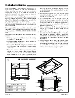
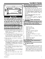
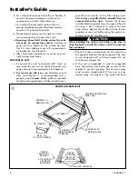
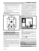
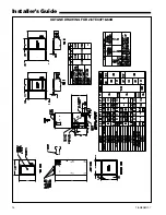
NOTE: If air handler is used WITHOUT a supplementary
electric heater, a sheetmetal plate is required to cover
the open hole in the airflow system. See Figure 2. Also
seal the cabinet air tight where the wire enters.
10. If the unit is installed without a return air duct, ap-
plicable local codes may limit this air handler to in-
stallation only in a single story residence and
within conditioned space.
11. If the outdoor unit is to be installed later, or by oth-
ers, then installation of the air handler must be
made to allow access for refrigerant lines, or attach
refrigerant lines to air handler when installing.
12. Make sure there are provisions for installing con-
densate drain lines.
13. If side, front or rear return is required, air handler
must be elevated or placed on a plenum
(TAYPLNM100 for 2/4TEC3F18 - 48B, 2/4TEC3F60B
or TAYPLNM101 for 2/4TEC3F55B). Connecting re-
turn duct directly to the side, front or rear of the
cabinet is not approved.
14. Route refrigerant and condensate drain lines away
from air handler so they do not interfere with ac-
cess panels and filters.
15. When external accessories are used, the additional
height and width requirements must be considered
in the overall space needed.
16. These units are not approved for outdoor installa-
tion.
17. These units are approved for draw-through appli-
cation only.
NOTE: No atomizing style humidifier is allowed in the
return plenum with the use of this unit.
18.
Flow-through Bypass Humidifiers
Excessive bypass air may cause water blow-off,
which will adversely affect system operation and air
cleaner performance. To verify bypass airflow, fol-
low the Bypass Humidifier Pre-Installation Check-
out and Set-Up Procedures available through your
local distributor. Ask for publication number 18-
CH37D1-1.
Steam and Flow-through Fan Power Duct-
mounted Humidifiers
Follow the humidifier installation instructions.
These should only be installed on the supply air
side of the system.
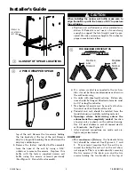
B. TWO PIECE CABINET DISASSEMBLY
(OPTIONAL)
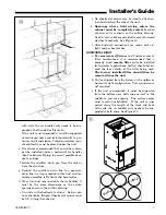
NOTE: For easier installation into tight areas, the 4
and 5 ton air handlers can be disassembled and reas-
sembled after moved to an attic or other space.
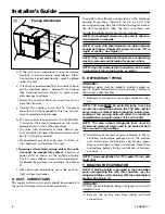
Steps for disassembly and reassembly (See Figures 3
and 4)
1.
Disconnect wiring.
2.
Remove center bracket.
3.
Remove blower assembly.
4.
Remove coil.
5.
Cut foil tape - minimum 3" foil tape.
6.
Remove top 8 screws. See Figure 3.
7.
Lift upper section.
8.
Set air handler in place.
9.
Attach screws - insure gaskets are aligned
along flange.
10.
Use foil tape to seal - use minimum 3" foil tape.
11.
Insert coil.
12.
Reinstall blower assembly.
13.
Reinstall center bracket.
14.
Reconnect wiring.
NOTE: In Downflow, remove coil before blower by
reversing steps 4 and 5.
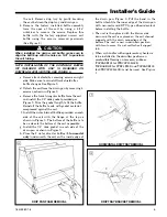
C. UNIT INSTALLATION
UPFLOW
a.
For maximum efficiency
, the horizontal drip
tray should be removed. See Figures 6, 7 and
8. Drip tray removal requires that the coil be
removed by sliding the coil out on the coil
channel supports. The drip tray is detached by
removing the two screws at the drain pan and
the two screws holding the two brackets at the
From Dwg. 21B140413
4"
6"
17"
1"
3/8"
1/4" HOLES (4)
ACCESSORY BAY99X123
IF AIRHANDLER IS USED
WITHOUT
A FACTORY FURNISHED
SUPPLEMENTARY HEATER, A PLATE IS REQUIRED TO COVER
THE OPEN HOLE IN THE AIR FLOW SYSTEM
2


