background image

6

18-BC52D5-5

Installer’s Guide

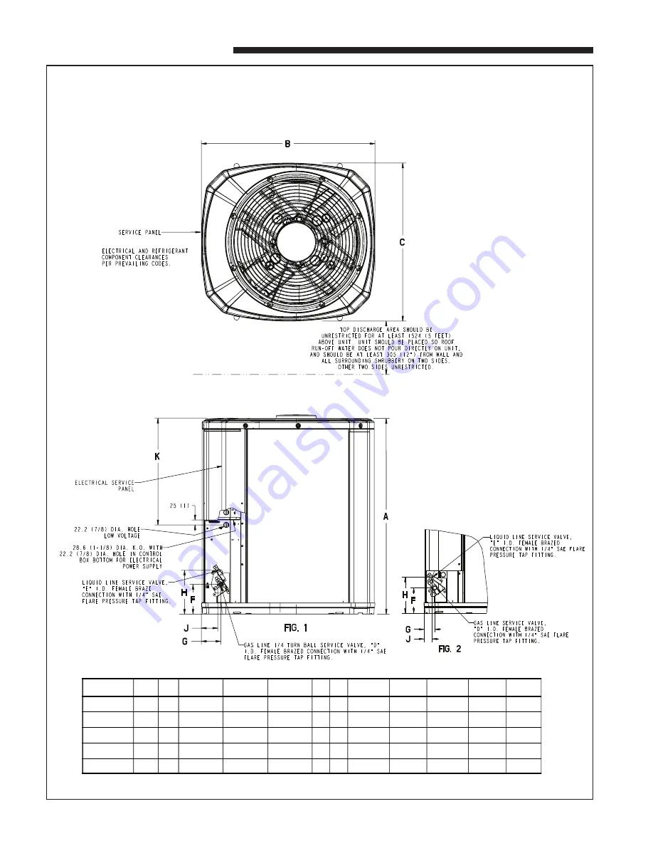
2TWB0012-036AA OUTLINE DRAWING

Note: All dimensions are in MM (Inches).

From Dwg. D153074  Rev. 15

MODELS

BASE FIG.

A

B

C

D

E

F

G

H

J

K

2TWB0012AA

2

2

651 (25-5/8) 724 (28-1/2) 651 (25-5/8) 5/8

1/4

127 (5)

57 (2-1/4) 181 (7-1/8) 44 (1-3/4)

457 (18)

2TWB0018AA

2

2

651 (25-5/8) 724 (28-1/2) 651 (25-5/8) 3/4 5/16

127 (5)

57 (2-1/4) 181 (7-1/8) 44 (1-3/4)

457 (18)

2TWB0024AA

2

2

730 (28-3/4) 724 (28-1/2) 651 (25-5/8) 3/4 5/16 137 (5-3/4) 65 (2-5/8) 210 (8-1/4) 57 (2-1/4)

457 (18)

2TWB0030AA

2

2

730 (28-3/4) 724 (28-1/2) 651 (25-5/8) 7/8

3/8 137 (5-3/4) 65 (2-5/8) 210 (8-1/4) 57 (2-1/4)

457 (18)

2TWB0036AA

3

2

832 (32-3/4) 829 (32-5/8) 756 (29-3/4) 7/8

3/8 137 (5-3/4) 86 (3-3/8) 210 (8-1/4) 79 (3-1/8)

508 (20)

Summary of Contents for 2TWB0012-036AA

Page 1: ...rise which are not covered sufficiently for the purchaser s purposes the matter should be referred to your installing dealer or local distributor A GENERAL The following instructions cover 2TWB0012 036AA Heat Pump Units NOTE These outdoor units may be used with indoor units equipped with Thermostatic Expansion Valve or Accutron Flow Control Check Valve F C C V assembly for refrigerant flow control...

Page 2: ...el in an envelope attached to the outdoor unit Outdoor unit nameplate will have correct orifice size specified as BAYFCCV A for rated performance D INSTALLING REFRIGERANT LINES Condensing units have provisions for flare connections Pressure taps are provided on the service valves of outdoor unit for compressor suction and liquid pressures The indoor end of the recommended refrigerant line sets may...

Page 3: ...into either valve pressure tap port thru the tubing and out the other port while brazing 8 Braze using accepted good brazing techniques LEAK CHECK IMPORTANT Replace pressure tap port valve core before attaching hoses for evacuation After the brazing operation of refrigerant lines to both the outdoor and indoor unit is completed the field brazed connections must be checked for leaks Pressurize thro...

Page 4: ...fy connections between the outdoor unit the thermostat and the indoor unit Table 1 NEC Class II Control Wiring 24 VOLTS WIRE SIZE MAX WIRE LENGTH 18 AWG 150 FT 16 AWG 225 FT 14 AWG 300 FT 8 Table 1 defines maximum total length of low voltage wiring from outdoor unit to indoor unit and to thermostat 9 Mount the indoor thermostat in accordance with instruc tion included with the thermostat Wire per ...

Page 5: ...ordance with procedures found in the Service Facts J ELECTRIC HEATERS Electric heaters if used are to be installed in the air han dling device according to the instructions accompanying the air handler and the heaters K OUTDOOR THERMOSTAT An outdoor thermostat TAYSTAT250B may be field installed For data see wiring diagram attached to unit and instruction sheet packaged with outdoor thermostat L SE...

Page 6: ... 4 181 7 1 8 44 1 3 4 457 18 2TWB0018AA 2 2 651 25 5 8 724 28 1 2 651 25 5 8 3 4 5 16 127 5 57 2 1 4 181 7 1 8 44 1 3 4 457 18 2TWB0024AA 2 2 730 28 3 4 724 28 1 2 651 25 5 8 3 4 5 16 137 5 3 4 65 2 5 8 210 8 1 4 57 2 1 4 457 18 2TWB0030AA 2 2 730 28 3 4 724 28 1 2 651 25 5 8 7 8 3 8 137 5 3 4 65 2 5 8 210 8 1 4 57 2 1 4 457 18 2TWB0036AA 3 2 832 32 3 4 829 32 5 8 756 29 3 4 7 8 3 8 137 5 3 4 86 3...

Page 7: ...18 BC52D5 5 7 Installer s Guide MOUNTING HOLE LOCATION Note All dimensions are in MM Inches NOTE For model base size see table on page 6 From Dwg 21D152989 Rev 0 ...

Page 8: ...RICAL Compressor O D Fan Won t Start Compressor Will Not Start But O D Fan Runs O D Fan Won t Start Compressor Hums But Won t Start Compressor Cycles on IOL I D Blower Won t Start DEFROST Unit Won t Initiate Defrost Defrost Terminates on Time Unit Icing Up W H A T T O C H E C K M O D E P O W E R S U P P L Y H I G H V O L T A G E W I R I N G C O M P R E S S O R I O L R U N C A P A C I T O R S T A R...

Reviews: