Page 21
Installer’s Guide
Service Maintenance
Cooling Season
To keep the unit operating safely and efficiently, the manufacturer
recommends that a qualified service technician check the entire
system at least once each year or sooner if needed. The service
technician should examine these areas of the unit:
〿
filters (for cleaning or replacement)
〿
motors and drive system components
〿
economizer gaskets (for possible replacement)
〿
safety controls (for mechanical cleaning)
〿
electrical components and wiring (for possible replacement
and connection tightness)
〿
condensate drain (for proper sealing and cleaning)
〿
unit duct connections (to see that they are physically sound
and sealed to the unit casing)
〿
unit mounting support (for structural integrity)
〿
the unit (for obvious unit deterioration)
Heating Season
Complete the following unit inspections and service routines
described at the beginning of each heating season.
〿
Visually inspect the unit to ensure that the airflow required
for combustion and condenser coil is not obstructed from the
unit.
〿
Inspect the control panel wiring to verify that all electrical
connections are tight and that the wire insulation is intact
ECM Fan Motor Adjustments
If the airflow needs to be increased or decreased, see the
Airflow Table in the SERVICE FACTS. Information on chang-
ing the speed of the blower motor is in the Blower Performance
Table. Blower speed changes are made on the ECM Fan Control
mounted in the control box. The ECM Fan Control controls the
variable speed motor. There is a bank of 8 dip switches, (See
Figure 21 below), located on the board. The dip switches work
in pairs to match the cooling/heat pump airflow (CFM/TON),
Fan off-delay options and electric heat airflow adjustment. The
switches appear as shown in the Figure below.
CFM
SELECTION
LIGHT
DIP
SWITCHES
CFM FAN
R W3 W2 W1
Y Y LO
J
21C800796P01
CNT03600
Figure 21. ECM Fan Control
Summary of Contents for 4TCY4024
Page 5: ...Page 5 Installer s Guide Figure 2 4TCY4024 through 4TCY4036 2 of 3...
Page 6: ...Page 6 Installer s Guide Figure 3 4TCY4024 through 4TCY4036 3 of 3...
Page 8: ...Page 8 Installer s Guide Figure 5 4TCY4042 through 4TCY4060 2 of 3...
Page 9: ...Page 9 Installer s Guide Figure 6 4TCY4042 through 4TCY4060 3 of 3...
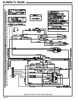
Page 18: ...Page 18 Installer s Guide Figure 20 Typical 4TCY4 Field Wiring Diagram...
Page 22: ...Page 22 Installer s Guide Notes...


