18-GE15D1-2
5
Installer’s Guide
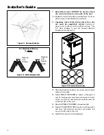
Figure 7. FIELD CHARGER Removal
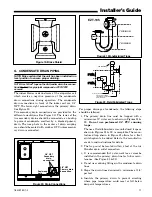
Figure 8. Protector Plate Removal
4.
The horizontal drip tray should be removed
for
maximum efficiency
. See Figures 9, 10, and 11.
a.
Remove the coil by sliding it out on the coil
channel supports. For the 4TEE3D05, 07, 09, & 10
units, there is a coil support tab at the top of the
coil, connected to the case, that must be removed
first.
b.
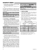
Remove 1" insulation strip covering the lip of
the drip tray. See Figure 9.
c.
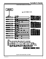
Detach the tray by removing the two screws at
the drain pan and the two screws holding the two
brackets at the top of the coil. See Figures 10 & 11.
d.
Remove drip tray by gently breaking the seal
between the drip tray and drain pan.
5.
Replace the factory installed baffle with supplied
narrow baffle. See Figure 12.
a.
Remove the factory installed baffle assembly
from the apex of the coil by using a 5/16" nutdriver
to remove the screws.
b.
Replace this baffle with the factory supplied nar-
row coil baffle using the screws removed previously.
See Figure 12.
6.
Position unit on Pedestal or other suitable founda-
tion. If Pedestal is not used, a frame strong enough
to support the total weight must be provided. Pro-
vide a minimum height of 14 inches for proper un-
restricted airflow. In open return applications, in-
stallation requires a BAYPLNM or TASB stand.
7.
If a return air duct is connected to the air handler,
it must be the same dimensions as shown in Figure
17 and the outline drawing on page 21.
8.
On units with sheetmetal returns the Return
plenum must be flanged, sheetmetal screws
must be 1/2" in length or shorter. Self-tapping
screws are supplied with the unit accessory
pack.
Figure 9. Remove Insulation Strip
Figure 10. Remove Screws at Drain Pan


