Service Facts
© 2013 Trane
NOTICE: The manufacturer has a policy of continuous product and product data improvement, and it
reserves the right to change design and specifications without notice.
IMPORTANT — This document contains a wiring diagram and service information. This is customer property and is to
remain with this unit. Please return to service information pack upon completion of work.
WARNING:
HAZARDOUS VOLTAGE- DISCONNECT POWER and DISCHARGE
CAPACITORS BEFORE SERVICING
SINGLE PACKAGED
GAS HEATING / ELECTRIC COOLING
4YCY4036B1075/1096B
PRODUCT SPECIFICATIONS
4YCY4036B-SF-1H
1
Certified in accordance with the Unitary
Air-Conditioner Equipment certification
program, which is based on AHRI
Standard 210/240. Sound Power val-
ues are not adjusted for AHRI 270-95
tonal corrections.
2
All models are certified to UL 1995.
Ratings shown are for elevations up to
2000 ft. For higher elevations reduce
ratings at a rate of 4% per 1000 ft.
elevation.
3
Convertible to LPG.
4
This value is approximate. For more
precise value, see Unit Nameplate.
5
Based on U.S. Government Standard
Tests.
6
Filters must be installed in return air
stream. Square footages listed are
based on 300 f.p.m. face velocity. If
permanent filters are used size per
manufacturer's recommendation with
a clean resistance of 0.05" W.C.
7
Standard Air - Dry Coil - Outdoor.
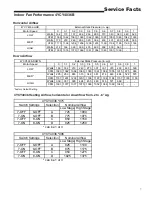
MODEL
RATED Volts/PH/Hz
Performance Cooling BTUH
Indoor Airflow (CFM)
Power Input (KW)
EER/SEER(BTU/Watt-Hr.)
Sound Power Rating [dB(A)]
Performance Heating
Input BTUH - 1st Stage (Natural Gas)
Input BTUH - 2nd Stage (Natural Gas)
AFUE
Temp. Rise — Min/Max (
°
F)
Orifice Qty / Drill Size (Natural Gas)
POWER CONN.—V/PH/HZ
Min. Brch. Cir. Ampacity
Fuse Size — Max. (amps)
Fuse Size — Recmd. (amps)
COMPRESSOR
Volts/Ph/Hz
R.L. Amps — L.R. Amps
OUTDOOR COIL — TYPE
Rows/F.P.I.
Face Area (sq.ft.)
Tube Size (in.)
INDOOR COIL — TYPE
Rows/F.P.I.
Face Area (sq.ft.)
Tube Size (in.)
Refrigerant Control
Drain Conn. Size (in.)
OUTDOOR FAN — TYPE
Dia. (in.)
Drive/No. Speeds
CFM @ 0.0 in. w.g.
7
Motor — HP/R.P.M.
Volts/Ph/Hz
F.L. Amps/L.R. Amps
INDOOR FAN — TYPE
Dia x Width (in.)
Drive/No. Speeds
CFM @ 0.0 in. w.g.
Motor — HP/R.P.M.
Volts/Ph/Hz
F.L. Amps/L.R. Amps
COMBUSTION FAN — TYPE
Drive/No. Speeds
Motor — HP/R.P.M.
Volts/Ph/Hz
FLA
FILTER / FURNISHED
Type Recommended
Recmd. Face Area (sq. ft.)
REFRIGERANT
Charge (lbs.)
GAS PIPE SIZE (in.)
DIMENSIONS
Crated (in.)
WEIGHT
Shipping (lbs.) / Net (lbs.)
4YCY4036B1075B
208-230/1/60
38000
1210
3.166
12.0 / 14.2
69
56250
75000
79.5
30 / 60
2 / #33
208-230/1/60
26.2
40
40
SCROLL
208-230/1/60
16.7 / 79
SPINE-FIN
2 / 24
15.49
3/8
PLATE FIN
4 / 15
3.54
3/8
EXPANSION VALVE
3/4 FEMALE NPT
PROPELLER
23.4
DIRECT / 1
3320
1/5 / 830
208-230/1/60
1.1 / 1.9
CENTRIFUGAL
10 X 10
DIRECT / VARIABLE
SEE FAN PERFORMANCE TABLE
1/2 / VARIABLE
200-230/1/60
4.3 / 4.3
CENTRIFUGAL
DIRECT / 2
1/45 / 2800/1500
208-230/1/60
0.34
NO
THROWAWAY
4
R410A
7.80
1/2
H X W X L
47.86 / 44.5 / 52.03
488 / 392
4YCY4036B1096B
208-230/1/60
38000
1210
3.166
12.0 / 14.2
69
72000
96000
80.0
40 / 70
3 / #37
208-230/1/60
26.2
40
40
SCROLL
208-230/1/60
16.7 / 79
SPINE-FIN
2 / 24
15.49
3/8
PLATE FIN
4 / 15
3.54
3/8
EXPANSION VALVE
3/4 FEMALE NPT
PROPELLER
23.4
DIRECT / 1
3320
1/5 / 830
208-230/1/60
1.1 / 1.9
CENTRIFUGAL
10 X 10
DIRECT / VARIABLE
SEE FAN PERFORMANCE TABLE
1/2 / VARIABLE
200-230/1/60
4.3 / 4.3
CENTRIFUGAL
DIRECT / 2
1/45 / 2800/1500
208-230/1/60
0.34
NO
THROWAWAY
4
R410A
7.80
1/2
H X W X L
47.86 / 44.5 / 52.03
493 / 397
Summary of Contents for 4YCY4036B-SF-1H
Page 9: ...9 Service Facts...
Page 12: ...Trane 6200 Troup Highway Tyler TX 75707 01 13...


