background image

8  

Service Facts

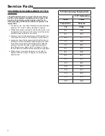
CHARGING IN COOLING ABOVE 55°F OD 

AMBIENT

The preferred method is to weigh in the factory charge 

per the unit nameplate. If weighing in the charge is not 

practical, the following method can be used. The fol-

lowing charging method is prescribed for systems with 

indoor TXVs.
  1.  For best results – the indoor temperature should be kept 

between 70°F to 80°F.  Add system heat if needed.

  2.  Whenever charge is removed or added, the system must 

be operated for a minimum 20 minutes to stabilize before 

accurate measurements can be made.

  3.  Measure Liquid Line Temperature and Refrigerant Pres-

sure at service valves in the compressor compartment.

  4.  Locate your liquid line temperature in the left column of 

the table, and the intersecting liquid line pressure under 

the subcool value column. Add refrigerant to raise the 

pressure to match the table, or remove refrigerant to 

lower the pressure.  Again, wait 20 minutes for the sys-

tem conditions to stabilize before adjusting charge again.

  5.  When system is correctly charged, you can refer to 

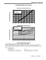
System Pressure Curves (on page 2) to verify typical 

performance.

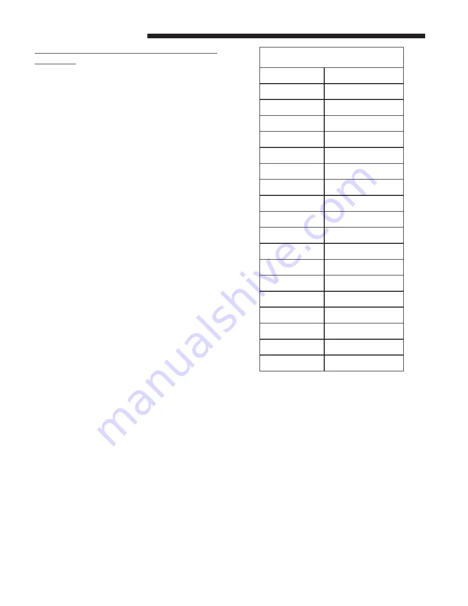
R-410A Subcooling Charging Table

10 (ºF) Subcooling

Liquid

Liquid 

Temperature

Pressure

(ºF)

PSIG

55

185

60

200

65

217

70

235

75

254

80

274

85

295

90

317

95

340

100

364

105

390

110

417

115

445

120

475

125

506

Summary of Contents for 4YCY4036B-SF-1H

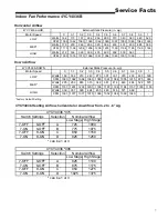
Page 1: ...p Rise Min Max F Orifice Qty Drill Size Natural Gas POWER CONN V PH HZ Min Brch Cir Ampacity Fuse Size Max amps Fuse Size Recmd amps COMPRESSOR Volts Ph Hz R L Amps L R Amps OUTDOOR COIL TYPE Rows F P...

Page 2: ...maintenance proceedures on the fan Operat ing the unit without the access panels properly installed may result in severe personal injury or death EXPLOSION HAZARD Propane gas is heavier than air and...

Page 3: ...TE INDOOR WET BULB 2 FIND INTERSECTION OF OD TEMP ID W B 3 READ LIQUID 4 OR SUCTION 5 PRESSURE IN LEFT COLUMN EXAMPLE 1 OUTDOOR TEMP 82 F 2 INDOOR WET BULB 67 F 3 AT INTERSECTION ACTUAL 4 LIQUID PRESS...

Page 4: ...4 Service Facts IMPORTANT Retain this wiring diagram please return this document to service information pack upon completion of work...

Page 5: ...5 Service Facts IMPORTANT Retain this wiring diagram please return this document to service information pack upon completion of work...

Page 6: ...ame as above 2nd stage heat has a 10 minute delay from the time of 1st stage ignition Comfort Control satisfied Safety Sequences Thisproductisequippedwithsafetydevicestoprotectagainst abnormal conditi...

Page 7: ...0 5 0 6 0 7 0 8 0 9 1 Watts 169 182 210 243 273 301 331 370 433 480 530 CFM 1025 1062 1068 1063 1060 1061 1064 1055 1015 975 990 Watts 225 253 283 315 348 381 414 449 484 522 575 CFM 1187 1201 1203 1...

Page 8: ...uid Line Temperature and Refrigerant Pres sure at service valves in the compressor compartment 4 Locate your liquid line temperature in the left column of the table and the intersecting liquid line pr...

Page 9: ...9 Service Facts...

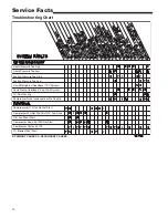
Page 10: ...High Suction Pressure Too Low Liquid Refrigerant floodback TXV System Liquid Refrig floodback Cap Tube System I D Coil Frosting Compressor Runs Inadequate or No Cooling Compressor O D fan Do Not Start...

Page 11: ...itch protection device open Steady ON Normal No Call for Heat 5 Flashes Flame sensed and gas valve not energized or flame sensed and no W signal 6 Flashes Flame Rollout Switch open 7 Flashes Thermosta...

Page 12: ...Trane 6200 Troup Highway Tyler TX 75707 01 13...

Reviews:

Related manuals for 4YCY4036B-SF-1H