3
AM7A0C36H31-SF-1A
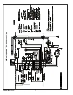
SEQUENCE OF OPERATION FOR *AM7A0C36H31SA
A7 Sequence of Operation
Abbreviations
• AFC – Airflow Control
• EVC – Expansion Valve Control
• EEV – Electronic Expansion Valve
• EHC – Electric Heat Control
• YI – Y signal from the comfort control
• YO – Y signal out of the AFC from the comfort control
• Y2 – Y2 signal from comfort control
This unit has a unique feature that receives 24VAC analog
inputs from a conventional comfort control and then
converts these inputs to serial communicating signals
between the different controls within the air handler.
The installing and servicing technician should have an
understanding of the sequence of operation to be able
to properly setup and diagnose functions of the air
handler.
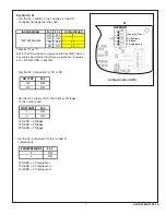
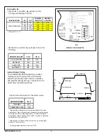
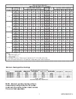
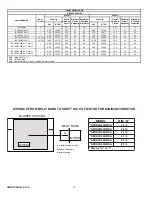
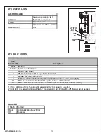
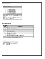
The dip switch settings on the control boards must be
properly set to obtain the correct sequence of opera-
tion. Reference the air handler and electric heat wiring
diagrams and dip switch configuration chart for ad-
ditional information.
Continuous Fan
IMPORTANT: If the indoor air exceeds 60% relative
humidity or simply feels uncomfortably humid, it is
recommended that the indoor fan only be used in the
AUTO mode.
1. R-G contacts close on comfort control sending 24VAC
to the G terminal of the AFC.
2. The AFC micro-processor sends a command to the
serial communicating blower motor to run at 50%.
See airflow Dip Switch settings for additional info.
Heatpump Od Single Stage (heating mode)
1. R-Y contacts close on the comfort control sending
24VAC to Y1 terminal on the AFC.
2. Normally closed contacts on the AFC will pass 24VAC
to the YO terminal providing power to the outdoor unit
control circuit.
3. R-G contacts close on comfort control sending 24VAC
to the G terminal of the AFC.
4. The AFC micro-processor sends a command to the
serial communicating blower motor to run at 100%.
5. The EVC will drive the EEV to the near closed position
and refrigerant will flow through the check valve.
Heatpump Od Two Stage (heating mode)
1. R-Y1 contacts close on the comfort control sending
24VAC to Y1 terminal on the AFC.
2. Normally closed contacts on the AFC will pass 24VAC
to the YO terminal providing power to the outdoor unit
1st stage control circuit.
3. R-G contacts close on comfort control sending 24VAC
to the G terminal of the AFC.
4. The AFC micro-processor sends a command to the
serial communicating blower motor to run at 1st stage
heating cfm.
5. The EVC will drive the EEV to the near closed position
and refrigerant will flow through the check valve.
6. R-Y2 contacts close on the comfort control sending
24VAC to Y2 terminal on the AFC.
7. The Y2 signal is passed through to provide power to
the outdoor unit 2nd stage control circuit.
8. The blower motor will run at 100% of the heating cfm.
Od Single Stage (cooling mode)
6. R-Y contacts close on the comfort control sending
24VAC to Y1 terminal on the AFC.
7. Normally closed contacts on the AFC will pass 24VAC
to the YO terminal providing power to the outdoor unit
control circuit.
a. Heatpump OD – R-O contacts close on the comfort
control sending 24VAC to the O terminal of the AFC.
The AFC communicates to the EVC that the system is
in cooling mode. The O signal is passed through to the
OD unit.
b. Non heatpump OD – OD dip switch configuration will
communicate to the EVC to control superheat on a Y
only signal.
8. R-G contacts close on comfort control sending 24VAC
to the G terminal of the AFC.
9. The AFC micro-processor sends a command to the
serial communicating blower motor to run at 100% of
the cooling cfm.
10. The EVC will receive input from the two temperature
sensors and start to control superheat.
Od Two Stage (cooling mode)
1. R-Y1 contacts close on the comfort control sending
24VAC to Y1 terminal on the AFC. The AFC communi-
cates to the EVC to control superheat for 1st stage.
2. Normally closed contacts on the AFC will pass 24VAC
to the YO terminal providing power to the outdoor unit
1st stage control circuit.
a. Heatpump OD – R-O contacts close on the comfort
control sending 24VAC to the O terminal of the AFC.
The AFC communicates to the EVC that the system is
in cooling mode. The O signal is passed through to the
OD unit.
b. Non heatpump OD – OD dip switch configuration will
communicate to the EVC to control superheat on a Y
only signal.
3. R-G contacts close on the comfort control sending
24VAC to the G terminal of the AFC.
4. The AFC micro-processor sends a command to the
serial communicating blower motor to run at the 1st
stage cooling cfm. (1st stage cooling cfm is a multiplier
of 2nd stage cfm)


