INSTALLER'S GUIDE
18-AH13D9-5A-EN
Page 3
5.
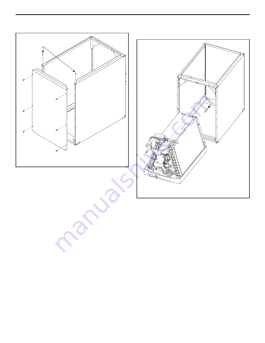
Fasten the back panel to the side panels as shown in
Figure 6.
For BAYCLE14XX and BAYCLE17XX, six (6) screws are needed
on the edges of this panel. For BAYCLE21XX and BAYCLE24XX,
ten (10) screws are required.
Near the top flange, use two (2) pop rivets to secure the back
panel to the side panels. You may use screws if the furnace unit
is an upflow model.
6.
Slide the coil and drain pan assembly inside the coil enclo-
sure until it stops against the back as shown in Figure 7.
Figure 6
Figure 7
Pop Rivets (2) (Screws
may be used only for
Upflow)


