-
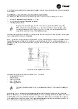
Position of thermostat casing: fastened on outside panel of AHU casing
-
Triggering temperature: set to 70°C
– value must not be changed
-
Sensor position: downstream of electric heater in upper area of airflow
-
Function: alarm stop in case of overtemperature because of missing airflow
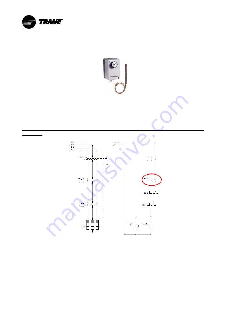
Figure 120:
Thermostat 2
Connection box may reach high temperatures. For connection use heat-resistant cables (admissi-
ble operation temperature min. 110°C), for example silicone, Teflon or glass fiber insulated cables.
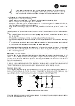
Connection scheme for electric heater according to the specified safety concept as minimum re-
quirement.
Figure 121:
Connection scheme for electric heater
In case of dehumidification wheel downstream of electric heater ensure that control rotates the
wheel while electric heater is on (additional enabling contact). If control is not supplied by TRANE,
this feature has to be ensured on responsibility of client.
7.6 Differential pressure restriction for plate heat exchangers
Enabling contact:
Fan is running
Summary of Contents for CCEB
Page 48: ...Figure 83 Pulling out the filters Figure 84 Pull out tool...
Page 74: ......

