background image

CGWH-SVX01D-E4

5

Installation

Unit nameplate

The unit nameplate gives the 
complete model reference numbers. 
The unit power rating is shown, and 
power supplies should not deviate by 
more than 5 % from the rated power.
Compressor motor amperage is 
shown in box I.MAX.
The customer’s electrical installation 
must be able to withstand this 
current.

Installation instructions

Foundations
No special foundations are required, 
provided the supporting surface is 
flat and level, and can withstand the 
weight of the unit.

Isolation rubber pads
They are supplied as standard with 
the machine, and should be placed 
between the supporting floor and 
the unit to isolate the unit from the 
ground (4 pads for the sizes 115 to 
125 and 6 pads for the sized 225 
to 250). To reduce vibration, Trane 
recommends the use of neoprene 
pads (not included) but does not 
allow the use of spring isolators.
Water drain hole
Install a drain hole wide enough to 
drain away water from the unit in the 
event of shut-down or repair.

Clearance
Respect recommended clearance 
around the unit to allow maintenance 
operation to take place without 
obstruction. Submittals are available 
on request from your local Trane 
Sales Office.

Handling

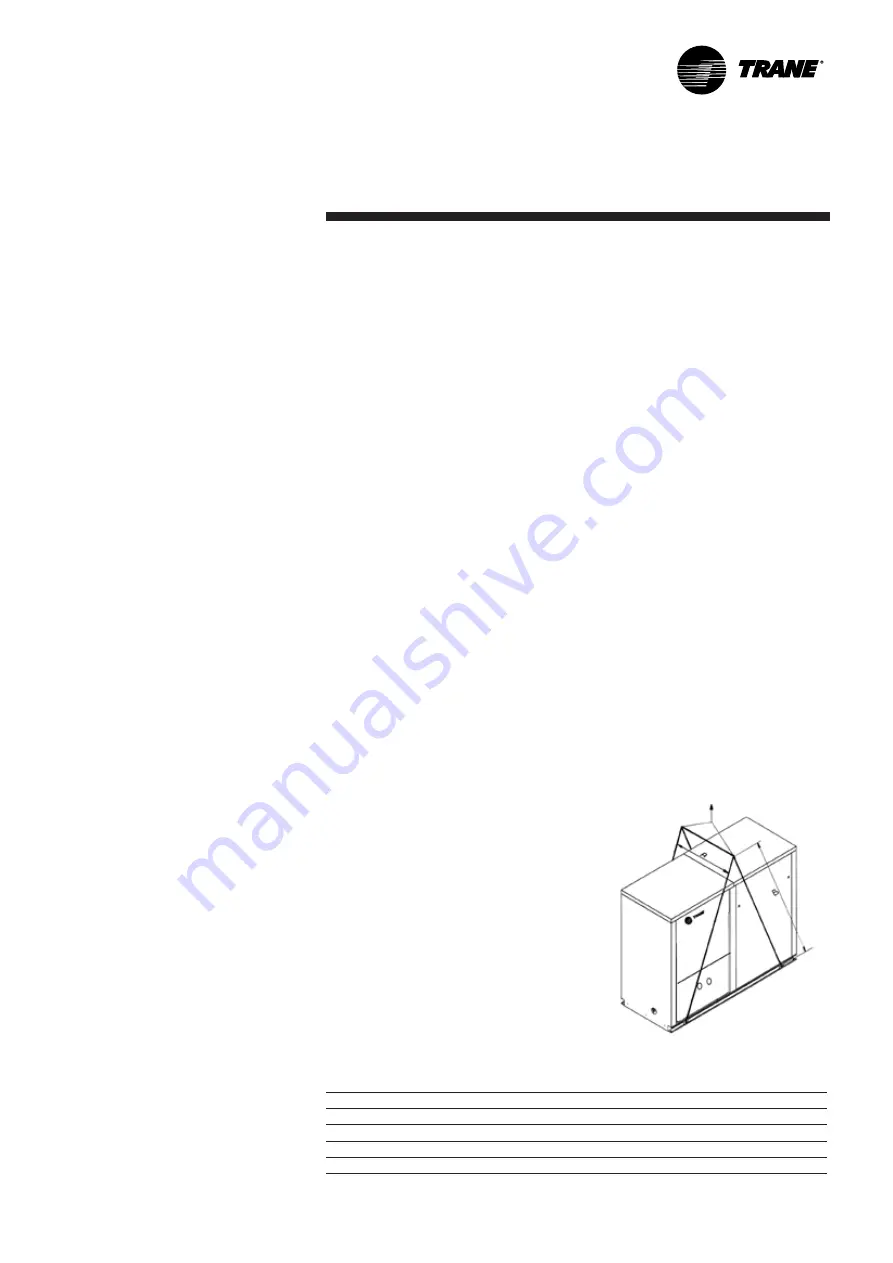
A specific lifting method is 
recommended as follows:

1.  4 lifting points are built into the 

unit.

2.  Slings and spreader bar to be 

provided by rigger and attached 
to the 4 lifting points.

3.  Minimum rated lifting capacity 

(vertical) of each sling and 
spreader bar shall be no less 
than the tabulated unit shipping 
weight.

CAUTION!
The plates welded at the end of the 

bases must not be used for handling. 

Use the ones at 237 mm from the 

ends.

Figure 1 - Handling

Table 1 - Dimensions of recommended slings and swing-bar :

Unit size

115

120

125

225

230

235

240

250

A (mm)

1400

1400

1400

1400

1400

1400

1400

1400

B (mm)

1900

1900

1900

1900

1900

1900

1900

1900

Weight (kg) CGWH

412

444

476

668

702

739

803

873

Weight (kg) CCUH

389

416

443

626

655

679

757

815

Summary of Contents for CCUH 115

Page 1: ...Operation Maintenance CGWH SVX01D E4 CGWH Packaged Water cooled liquid chiller CCUH Condenserless liquid chiller Sizes 115 120 125 225 230 235 240 250 To be used with the user guide of CH530 scroll chiller controls ...

Page 2: ...void death injury equipment or property damage the following recommendations should be observed during maintenance and service visits 1 The maximum allowable pressures for system leak testing on low and high pressure side are given in the chapter Installation Always provide a pressure regulator 2 Disconnect the main power supply before any servicing on the unit 3 Service work on the refrigeration ...

Page 3: ... environmental regulations impacting installation operation and disposal of the equipment in particular need to recover environmentally harmful substances refrigerant oil antifreeze agents etc Do not vent into the atmosphere any refrigerant The handling of refrigerant shall be fulfilled by a qualified service engineer With regards to the refrigerant charge contained in this chiller the F gas regul...

Page 4: ...r 8 Winter freeze protection 10 Water treatment 11 Compressor sequencing 11 Interconnection between CCUH and remote condenser 12 Electrical connections 12 General data 14 General start up Preparation 16 Start up 16 Operation Control and Unit Operation 21 Weekly start up and week end shutdown 21 Seasonal shutdown and start up 21 Maintenance Maintenance instructions 22 Installation checklist 23 Trou...

Page 5: ...lators Water drain hole Install a drain hole wide enough to drain away water from the unit in the event of shut down or repair Clearance Respect recommended clearance around the unit to allow maintenance operation to take place without obstruction Submittals are available on request from your local Trane Sales Office Handling A specific lifting method is recommended as follows 1 4 lifting points a...

Page 6: ...8 Strainer avoid getting heat exchangers dirty All installation must be equipped with efficient strainer in order that only clean water enters into exchanger If there is no strainer reserve will be formulated by the Trane technician at the start up of the unit The strainer used must be able to stop all particles with a diameter greater than 1 6 mm 9 Draining and charging used to drain and charge t...

Page 7: ...d repair defective component Repeat test process to check that the repair can withstand rated pressure NOTE CCUH is delivered with a nitrogen holding charge and isolating valves The minimum volume can be determined by using the following formula Volume Cooling capacity x Time x highest capacity step Specific heat Dead band Minimum operating time 120 seconds Specific heat 4 18 kj kg Average deadban...

Page 8: ...ation It includes its own high pressure protection set at 23 bar The party in charge of the supply of the condenser and of its refrigerant piping is responsible for implementing all required protections to comply with PED requirements for the design pressure of the condenser installed Refer to the document PROD SVX01_ XX delivered with this chiller to check all the mandatory conformity requirement...

Page 9: ...d discharge line diameter CCUH circuit 2 for vertical risers Leaving chilled water temperature C Unit size 12 10 8 6 4 2 0 2 4 6 8 10 12 14 225 7 8 1 1 8 230 7 8 1 1 8 235 7 8 1 1 8 240 7 8 1 1 8 1 3 8 250 7 8 1 1 8 1 3 8 Table 7 Required discharge line diameter CCUH circuit 1 either vertical or horizontal Leaving chilled water temperature C Unit size 12 10 8 6 4 2 0 2 4 6 8 10 12 14 115 5 8 7 8 1...

Page 10: ...to internal refrigerant migration if the condenser circuit is maintained at a low temperature below 0 C for a long period during the cold season If necessary provide isolation valves on the condenser water circuit CGWH CCUH is protected against refrigeration migration by a liquid solenoid valve Recommended ethylene and propylene glycol percentage are indicated in the General Start up section Loadi...

Page 11: ...ncing Tables 9 and 10 show compressor sequencing at the start of the unit Balanced means that there is no fixed sequence Compressors are started in order to balance compressor total running times Table 9 Unit Model Unit size COMPRESSOR LOCATION Recommended Sequence Number of capacity stages Circuit 1 Circuit 2 1 2 3 4 Circuit 1 Circuit 2 CGWH 115 10 T 10 T Balanced 2 120 10 T 15 T 3 125 15 T 15 T ...

Page 12: ...close to the unit 2 Only copper wiring should be used Using aluminium wires can produce galvanic corrosion and possibly lead to superheat and failure of connection points Trane provides a single power supply which includes the transformer Warranty reserves will be formulated if a transformer not supplied by Trane is installed inside the electric panel Interconnection between CCUH and Remote Conden...

Page 13: ...ns 6 1 2 3 3 4 4 4 Two fan speed first fan 1 3 3 4 4 4 Single speed only fans Table 12 Fan staging Example 4 fans per circuit single speed CCUH Standard 4 fans per circuit Relays Energized Stage Number of Fans 1 2 3 4 Capacity 0 0 0 0 0 0 0 1 1 1 0 0 0 25 2 2 1 0 1 0 50 3 3 0 0 1 1 75 4 4 1 0 1 1 100 Table 13 Fan staging Example 4 fans per circuit with first fan 2 speed CCUH Low Ambient 2 Speed 4 ...

Page 14: ...ber of speeds 1 1 1 1 1 1 1 1 Number of motors 1 1 1 1 1 1 1 1 Rated Amps 2 4 A 30 42 50 55 65 75 84 101 Locked rotor Amps 2 A 120 175 175 175 175 175 175 175 Motor RPM rpm 2900 2900 2900 2900 2900 2900 2900 2900 Sump Heater W 10T compressor 100W 15T compressor 160W Evaporator Number 1 1 1 1 1 1 1 1 Type Brazed plate Water volume total l 4 7 5 9 7 0 8 9 10 3 12 3 12 3 16 1 Antifreeze Heater W Evap...

Page 15: ...5 175 Motor RPM rpm 2900 2900 2900 2900 2900 2900 2900 2900 Sump Heater 2 W 50W 400V Evaporator Number 1 1 1 1 1 1 1 1 Type Brazed plate Model V45 40 V45 50 V45 60 DV47 74 DV47 86 DV47 102 DV47 102 DV47 Water volume total l 4 7 5 9 7 8 9 10 3 12 3 12 3 16 1 Antifreeze Heater W Evaporator Water Connections Type ISO R7 Male Diameter 1 1 1 2 2 2 2 2 Discharge and liquid connections Type Brazed Female...

Page 16: ...op through evaporator is in accordance with the Trane order write up See Tables 14 15 On start up of each motor in the system check the direction of rotation and operation of all the components they drive Water flow control checking decrease the water flow and check the electrical contact in the control panel Check that there is sufficient demand for cooling on the day of start up around 50 of nom...

Page 17: ...eters statement Switch on main power supply switch Start the water pump s Start up the unit with the CH530 by pushing Auto The unit and the chilled water pumps contactor must be connected After unit start up leave in operation for at least 15 minutes to insure pressures are stabilized Then check voltage compressors currents leaving and return chilled water temperature suction temperature and press...

Page 18: ...voltage on the compressor nameplate Excessive emulsion of the oil in the compressor shows that refrigerant is present in the oil and the result will be that compressor is not lubricated enough Shut down compressor and consult Trane technician Excess oil in compressor can damage the compressor Before adding oil consult Trane technician Use only Trane products recommended The compressors must operat...

Page 19: ...2 5 64 6 30 6 76 7 65 7 65 9 20 100 4 21 5 28 6 30 7 07 7 57 8 62 8 62 10 38 Table 19 Evaporator pressure drop filter tamis type 202 CGWH CCUH DP kPa Water flow l s CGWH CCUH 115 CGWH CCUH 120 CGWH CCUH 125 CGWH CCUH 225 CGWH CCUH 230 CGWH CCUH 235 CGWH CCUH 240 CGWH CCUH 250 10 1 06 1 26 1 43 1 61 1 70 1 77 1 96 2 23 20 1 48 1 76 1 98 2 27 2 38 2 51 2 82 3 21 40 2 07 2 45 2 76 3 19 3 35 3 55 4 05...

Page 20: ...put water kW found in Tables 1 4 3 Water Flow Evaporator with glycol Litres sec F FLEVP x Cooling capacity with glycol kW x 0 239 x 1 Delta T Evaporator C 4 Water Pressure drop Evaporator with glycol kPa F PDEVP x Water Pressure drop Evaporator water kPa found in Table 16 CGWH Only 5 Water Flow Condenser with glycol Litres sec F FLCDS x Cooling capacity with glycol kW Power input with glycol kW x ...

Page 21: ... is required Carry out leak test Carry out oil analysis Record operating pressures temperatures amperages and voltage Check operation of machines compare conditions of operation against original commissioning data Stop the unit with the CH530 by pushing Stop Insure that all the safeties are taken to protect the compressor against refrigeration migration Fill out the visit log sheet and review with...

Page 22: ...esence is required Check operational set points and performance Calibrate controls Check operation of all safety devices Inspect contacts and tighten terminals Megger the motor compressor windings Record operating pressures temperatures amperages and voltage Carry out leak test Check configuration of unit control module Carry out oil analysis Change the oil as required based upon results of the oi...

Page 23: ...thermometer positioning o Check manometer positioning o Check chilled water flow rate balancing system o Check rinsing and filling of chilled water pipes o Check pump operation and water flow Electrical equipment o Check direction of rotation of compressors o Check chilled water pump drive rotation o Check installation and rating of mains power switch fuse o Check that electrical connections compl...

Page 24: ...m q Check presence of strainer ahead of evaporator q Check the tightness of the water circuit q Check rinsing and filling of chilled water pipes q Check pump operation and water flow Electrical equipment q Check installation and rating of mains power switch fuses q Check that electrical connections comply with specification q Check that electrical connections are in accordance with information on ...

Page 25: ...open Locate regulation device which has tripped out and see why See instructions concerning this device Replace compressor Compressor does not run Compressor motor groans High pressure switch tripped to contacts open on high pressure Discharge pressure too high Compressor sticking damaged or sticking components Discharge pressure too high See instructions for discharge pressure high B Compressor s...

Page 26: ...ine abnormally cold a Uneven liquid flow b Expansion valve locked in open position a Check superheat setting and fixing of expansion valve bulb b Repair or replace G Insufficient cooling capacity Thermostatic expansion valve whistles Not enough refrigerant Check refrigerant circuit tightness and add refrigerant Excess pressure drops through filter drier Drier filter clogged Replace Excessive super...

Page 27: ...en position a Check for superheat and check that expansion valve bulb is secure b Replace J Suction pressure too low Excessive pressure drop through filter drier Refrigerant does not flow through thermostatic expansion valve Drier filter clogged Expansion valve bulb has lost its refrigerant Replace the deshydrator Replace the bulb Loss of power Expansion valve obstructed Replace Superheat too low ...

Page 28: ...vanced controls and HVAC systems comprehensive building services and parts For more information visit www Trane com Trane has a policy of continuous product and product data improvement and reserves the right to change design and specifications without notice 2013 Trane All rights reserved CGWH SVX01D E4_0213 Supersedes CGWH SVX01C E4_1111 We are committed to using environmentally conscious print ...

Reviews: