22
Pre-Start-up
Voltage Range
The power supply of the unit must comply with the operating power supply marked on the
nameplate of this unit, and the supply voltage and the voltage imbalance between phases must
be within the following scope. The voltage between phases shall be measured, and the voltage
reading must be within the allowable voltage tolerance (
±
10%) shown on the nameplate of
this unit. If the voltage between any two phases is not within this tolerance, the electric power
company shall be notified to improve before operate this unit. Improper voltage will result in
the disorder of control function and shorten the service life of various electrical components and
compressor motors.
Voltage Imbalance
If the voltage imbalance between any two phases in the three-phase power system is too high, it
will cause motor overheating and motor failure. The maximum permissible imbalanced voltage
is 2%, and the voltage imbalance is defined as follows:
Voltage imbalance % =
100x|Va-Vd|
Va
Wherein
Va=(V1+V2+V3)/3(average voltage)
V1,V2,V3
=
line-to-line voltage
Vd
=
maximum line-to-line voltage deviated from Va
Water Flow
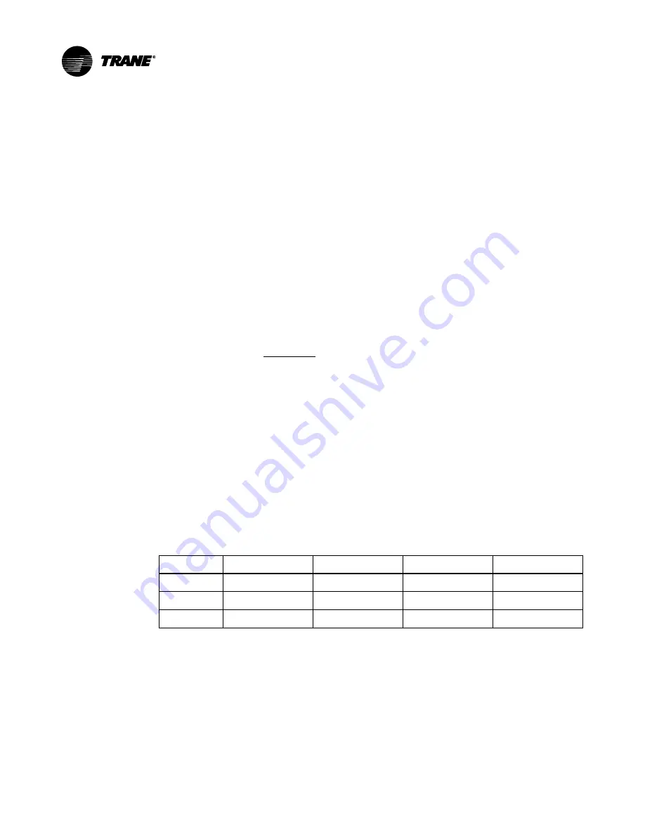
The chilled water flow through the unit must be between the upper and lower limits listed in
Table 1
. If the chilled water flow entering the evaporator is lower than the lower limit, it will
cause discontinuous flow, reduce the heat transfer effect and cause the expansion valve out of
control or abnormal low pressure shutdown. On the contrary, if the water flow is higher than the
upper limit, the parts and components inside the evaporator will be eroded.
Table 1. Water Flow
Unit: m
3
/h
Type
Lower flow limit
Rated flow
Upper flow limit
Pipe diameter
CX(G)AJ045
4.64
7.74
10.84
DN125
CX(G)AJ065
6.71
11.18
15.65
DN125
CX(G)AJ130
13.4
22.4
31.6
DN125
Water Pressure Drop
The water pressure difference between the water inlet and outlet ends of the unit is measured
to obtain the external head under this water volume, and this external head shall be basically
shown in External Head Curve. If the standard unit including the water pump is used, refer to
External Head Curve for the design of the pipeline system. If the unit (the water pump is installed
outside the unit) excluding the water pump is used, the internal water pressure drop of the unit
shall be basically shown in Unit Water Pressure Drop Curve. If the unit excluding the water pump
is used, refer to Unit Water Pressure Drop Curve for the design of the pipeline system.


