background image


51

Troubleshooting

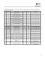
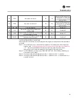
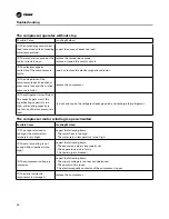
17 fault input alarm switches, 1 fault output alarm switch and 1 operating status output switch are arranged for the 
double-compressor system.

No.

Input Port

Fault Description

Type

Code

Fault Handling

1

TH1

Short circuit / open circuit of water inlet 

temperature sensor

A

SE

Turn off all external devices

2

TH2

Short circuit / open circuit of water 

outlet temperature sensor

A

SL

Turn off all external devices

3

TH3

Short circuit / open circuit of suction 

temperature sensor 1

A

Sd

Turn off all external devices

4

TH4

Short circuit / open circuit of defrosting 

temperature sensing sensor 1

A

S1

Turn off all external devices

5

TH5

Short circuit / open circuit of defrosting 

temperature sensing sensor 2

A

S2

Turn off all external devices

6

TH6

Short circuit / open circuit of suction 

temperature sensor 2

A

S3

Turn off all external devices

7

OVHT/HP2

High pressure alarm of compressor 2

E

H2

Only switch off the compressor 

2

8

FLOW

Lack of water flow

D

FL

Turn off all external devices

9

OV-PUMP

Overload of water pump 1

B

OP

Turn off all external devices

10

OV-FAN

Overload of fan

B

OF

Turn off all external devices

11

OV-COMP1

Overload of compressor 1

C

C1

Only switch off the compressor 

1

12

OV-COMP2

Overload of compressor 2

E

C2

Only switch off the compressor 

2

13

HP1

High pressure voltage of compressor 1

C

H1

Only switch off the compressor 

1

14

LP1

Low pressure voltage of compressor 1

C

L1

Only switch off the compressor 

1

15

FREZ/LP2

Low pressure voltage of compressor 2

E

L2

Only switch off the compressor 

2

16

 /  /  /

Low refrigeration water outlet 

temperature

D

E3

Switch off the compressor. The 

auxiliary heater for the water 

pump operates.

17

 /  /  /

Low suction temperature

D

E4

Switch off the compressor. The 

auxiliary heater for the water 

pump operates.

Summary of Contents for CGAJ series

Page 1: ...e installation start up and maintenance of heating ventilating and air conditioning unit will be hazardous and the operator shall have specific knowledge and training Improper installation adjustment...

Page 2: ...y Precautions 4 Nomenclature 5 Dimensions 6 Performance Data 7 Unit Installation 9 Electrical Installation 15 Wiring Diagram 17 Pre Start up 22 Unit Operation 29 Module Control System 35 Building Cont...

Page 3: ...ly and follow them Danger Indicates a potentially hazardous situation which if ignored could result in death or serious injury Warning Indicates a potentially hazardous situation which if ignored coul...

Page 4: ...t any time Sitting on the direct air duct is not conducive to your health and safety In order to prevent the relief valve failure due to calcification fouling and blockage the user should check the va...

Page 5: ...z 3PH Digit 9 Design Sequence B Digit 10 Fan speed 1 single speed Digit 11 Energy efficiency unit type N standard efficiency H High efficiency Digit 12 Controller S modular controller units 2 U unit c...

Page 6: ...ore BEFORE SERVICING INCLUDING REMOTE DISCONNECTS DISCONNECT ALL ELECTRIC POWER HAZARDOUS VOLTAGE WARNING KW KW A A A KW KW A A B V Hz MPa MPa m3 h m3 h kg dB A kg 50 1426 2145 1987 613 2038 1476 2020...

Page 7: ...11 2 22 4 pressure loss kPa 40 40 68 40 40 68 Water pipe flange mm DN125 DN125 DN125 DN125 DN125 DN125 Air side Type of heat exchanger High efficient fin type heat exchanger Quantity of fans Piece 2...

Page 8: ...ressure loss kPa 41 60 75 46 60 75 Water pipe flange mm DN125 DN125 DN125 DN125 DN125 DN125 Air side Type of heat exchanger High efficient fin type heat exchanger Quantity of fans Piece 2 2 4 2 2 4 Ra...

Page 9: ...upply voltage shall not be more than 10 Hoisting Please use a forklift or crane with proper tonnage to handle this unit to its installation location Hoisting method Table of External Dimensions and We...

Page 10: ...severe personal Failure to disconnect power before BEFORE SERVICING INCLUDING REMOTE DISCONNECTS DISCONNECT ALL ELECTRIC POWER HAZARDOUS VOLTAGE WARNING Installation Space Diagram PUMP WATER OUTLET WA...

Page 11: ...nnection units at most Note CXAJ CGAJ045 065 single module combination includes 4 direct return connection units at most and CXAJ CGAJ130 single module combination includes 2 direct return connection...

Page 12: ...ly pipeline of the unit The pipe components may vary with the locations of connectors and water source To avoid damaging the unit do not reversely install the system water pipe The water inlet pipe mu...

Page 13: ...t be equipped with the filters which can filter the particles with the diameter larger than 1 mm to ensure that the impurities cannot enter the evaporator Never use the untreated or improperly treated...

Page 14: ...pressure inside the system pipeline when the ambient temperature changes and prevent the pneumatic hammer from occurring in the pipeline a pressure water tank is added on the pipe system 2 To avoid t...

Page 15: ...To prevent injury or death disconnect electrical power supply before completing wiring connections to the unit Caution The terminals can be connected only through the copper conductors so as to avoid...

Page 16: ...of No 2 fan FLA Rated current of No 3 fan FLA Rated current of No 4 fan FLA Minimum circuit current of unit MCA Recommended fuse specification REC Maximum specification of fuse MFS Minimum specificati...

Page 17: ...AL N TH2 TH1 TH3 TH4 TH5 TH6 690134120001 C H RUN OUT IN EN SAVE N COM AL OUT IN H FAN PUMP A HAT HT EV1 COMP CCH MF MC 4WV TB HP LP OVP OVF MP FS OVC MF2 MF2 MC1 2 MC2 1 MC2 2 15 16 Wiring Diagram c...

Page 18: ...tion C H MF C H EN SAVE AL FAN PUMP HT EV COMP CCH MF MC 4WV TB HP OVP MP FS OVC Compressor Location HP HT EV MC2 AL U N LP Power Water Inlet Sensor Water Outlet Sensor Defrost Sensor1 Defrost Sensor2...

Page 19: ...IN H FAN PUMP A HAT HT EV1 COMP CCH MF MC 4WV TB HP LP OVP OVF MP FS OVC MF2 MF2 MC1 2 MC2 1 MC2 2 4WV1 4WV2 16 Wiring Diagram connected network and module mode Compressor Location Reserved control s...

Page 20: ...20 Wiring Diagram Wiring Diagram CX G AJ130 H Type...

Page 21: ...21 Wiring Diagram Wiring Diagram CX G AJ045 065 H Type...

Page 22: ...illed water flow through the unit must be between the upper and lower limits listed in Table 1 If the chilled water flow entering the evaporator is lower than the lower limit it will cause discontinuo...

Page 23: ...hilled water system Inspect for leakage at all pipe connections Adjust the water flow in the chilled water circuit and inspect the external water pressure for the standard unit or evaporator pressure...

Page 24: ...ow m3 h Water Flow m3 h Internal Pressure Drop of Unit 6 7 8 9 0 1 2 3 4 5 6 71 7 83 8 94 10 06 11 18 12 30 13 42 14 53 15 65 CX G AJ045 CX G AJ065 CX G AJ130 Internal Pressure Drop of Unit 0 1 2 3 4...

Page 25: ...he unit The definition of each bit is shown in the following table in which Bit4 only effective for the double compressor unit Bit1 Bit2 Bit3 Bit4 Bit5 Bit6 Bit7 Bit8 Mode C H Fan type EnSave Control...

Page 26: ...g Number SW1 Switch 1 2 3 4 5 0 the centralized controller displays A0 OFF OFF OFF OFF OFF 1 the centralized controller displays A1 ON OFF OFF OFF OFF 2 the centralized controller displays A2 OFF ON O...

Page 27: ...this function is invalid when module control is selected Control 0 Single unit control 1 Module control Bit Function Switch HType Unit Set through Single Unit Controller Centralized Controller etc Bit...

Page 28: ...45 065 130 OFF OFF OFF OFF OFF ON OFF OFF Bit1 5 and Bit8 of SW1 need adjust by actual jobsite Operating Parameter Setting The unit protection parameters and the operating parameters can be set in the...

Page 29: ...e inspection of circuit superheat If the superheat is normal but the sub cooling degree is abnormal please contact the professional maintenance personnel 7 If the system leakage is found the leakage p...

Page 30: ...t When the chilled water is circulated in the water system inspect whether all pipe connectors leaks or not 5 Adjust the water flow of the chilled water pipe through the balance valve and inspect the...

Page 31: ...not performed during the defrosting period This protection is allowed to occur once at most within 1 hour if this protection occurs twice within 1 hour shut down and give an alarm and display the cod...

Page 32: ...or equal to 0 and the set heating temperature is lower than 45 the set heating temperature will be automatically changed to the factory set value 45 Flow protection To avoid the evaporator freezing ca...

Page 33: ...n temperature is reduced to 37 No 1 compressor will be started Unless the unit is shut down the water pump will keep running Single system The operation of water pump fan and compressor for the single...

Page 34: ...water outlet temperature is lower than or equal to 43 two compressors will be allowed to be started if the water outlet temperature is lower than or equal to 42 three compressors will be allowed to be...

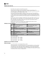
Page 35: ...en and 15 keys provides a clear operation interface bringing convenience to the users The casing of the centralized controller is provided with a flip cover the common keys such as OK and are exposed...

Page 36: ...control mode it indicates enabled or disabled of comfort control S23 Fresh air S24 Much air dust S25 Swing S26 High carbon dioxide content S27 Sleep S28 Day of Week S29 Timing On icon S30 Time displa...

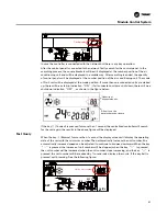
Page 37: ...month setting This key can be also used as a number key Week key After the centralized controller selects the single unit operation mode press this key to set the sleep mode When adjusting the time o...

Page 38: ...h key day of week key date key hour key minute key Single unit operation temperature setting keys and mode key sleep key fan speed key alarm reset key Group operation mode keys and startup shutdown ke...

Page 39: ...75 mm2 the twisted pair shall be provided with the shielding layer and the twist distance shall not be more than 5 cm It is recommended to use BELDEN 5320FE 2 Requirements of hand by hand wiring each...

Page 40: ...ustment the mode adjustment etc of each unit can be performed by phone Definition of Switch Functions OFF ON SW1 1 Indoor unit and outdoor unit interlocked control Indoor unit and outdoor unit not int...

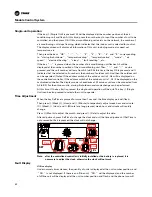
Page 41: ...tdown indication OFF as shown in the figure below Quantity of connected units All units on the network are shut down If the key Connect is pressed for more than 1 second the centralized controller wil...

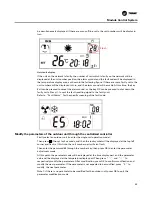
Page 42: ...ddress switch of the outdoor unit is 1 A1 ill be displayed on the centralized controller The display mode is hexadecimal 32 outdoor units can be connected from A0 to BF For the outdoor units startup s...

Page 43: ...ecific meaning of the fault code Modify the parameters of the outdoor unit through the centralized controller Firstly select an outdoor unit to enter the single unit operation mode Then press Group fo...

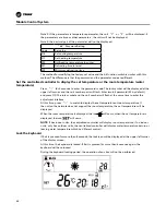
Page 44: ...art will flash Enter two bit password 00 by default and press OK The lock symbol and the unit number will flash at the same time to enter the adjustment interface At this time press to switch to displ...

Page 45: ...ions can be performed If Exit is pressed return to the temperature controller operation of the single indoor unit Module Control The single unit cascade system is a system which can realize the centra...

Page 46: ...er 8s but the host unit will not execute this shutdown command and only accept the single unit shutdown command Do not start up any host unit or slave unit or switch the mode by using the single unit...

Page 47: ...sponds to the condition 2 and the group 5 corresponds to the condition 1 The addition of parameter 2 following the condition change command expresses that the group 1 corresponds to the condition 3 an...

Page 48: ...he multi master controller system is suitable for the control of multiple units for the small commercial system This centralized control system is composed of a centralized controller a Modbus communi...

Page 49: ...the water return temperature is higher than or equal to the set value minus 2 turn off the electrical heater See Operation Manual for CXAJ Series Modbus Module for the specific wiring and operation o...

Page 50: ...circuit open circuit of defrosting temperature sensing sensor A S1 Turn off all external devices 5 OVHT HP2 Overload of electrical heater B H2 Turn off all external devices 6 FLOW Lack of water flow...

Page 51: ...of suction temperature sensor 2 A S3 Turn off all external devices 7 OVHT HP2 High pressure alarm of compressor 2 E H2 Only switch off the compressor 2 8 FLOW Lack of water flow D FL Turn off all exte...

Page 52: ...t coil heating outlet temperature B 1 29 29 Switch off 2 11 TH11 No 11 analog sensor fault coil heating outlet temperature B 2 2A 2A Switch off 2 12 TH12 No 12 analog sensor fault total water outlet t...

Page 53: ...E None Switch off Fault CodeTable for Main Control Panel Note the faults in this table are only displayed on the single unit controller and the centralized controller Note 1 when this fault occurs swi...

Page 54: ...gerant is insufficient to cause the low pressure switch to trip d The water valve is not opened to cause the flow switch or antifreezing switch to trip e The protective contact inside the fan trips f...

Page 55: ...ct the following items a The starting capacitor is poor b The starting relay is poor The second compressor cannot be started Possible Cause Handling Method 1 There is no refrigeration or heating signa...

Page 56: ...oo high sub cooling capacity is too low and the low pressure is low Find out and repair the refrigerant leakage point and recharge the refrigerant The compressor motor winding is open circuited Possib...

Page 57: ...or replace the expansion valve 5 The water flow of the evaporator is too low Inspect the filter screen and adjust the water flow 6 There is noncondensing gas in the system Recharge the refrigerant af...

Page 58: ...or control element 4 Operate below the minimum operating environment temperature Provide the proper exhaust pressure control or ambient temperature locking switch The exhaust pressure is too high Poss...

Page 59: ...low the minimum operating environment temperature Install an ambient environment disconnecting switch 4 The expansion valve is disabled Replace the expansion valve The high pressure is too high heatin...

Page 60: ...l be performed by qualified professionals In order to prolong the service life of the unit and reduce the possibility of failure please regularly perform the necessary maintenance for the unit Please...

Page 61: ...ean the condenser with steam otherwise it will lead to the rise of internal pressure to cause the refrigerant to leak through the relief valve Cleaning of shell and tube heat exchanger Trane recommend...

Page 62: ...des a complete set of advanced control and thermal energy air conditioning system comprehensive building services and spare parts support Please visit www trane com Trane constantly improves and innov...

Reviews: