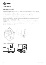
10
4
UNT-PRC002-GB
Technical Data
FWD
08
12
20
30
45
Power supply
(V/Ph/Hz)
230/1/50
Capacities
Cooling capacity on water (1)
(kW)
5,2
8,3
15
18,8
30,1
Heating capacity on water (2)
(kW)
6,3
11,9
18,9
20,9
38,2
Fan motor
(type)
2 x direct drive centrifugal
Fan power input (3)
(kW)
0,23
0,46
0,65
1,04
1,51
Current amps (3)
(A)
1,1
2,2
3,1
4,7
5,5
Start-up amps
(A)
3,2
5,5
9,3
14,1
16,5
Air flow
minimum
(m
3
/h)
490
980
1400
1800
2700
nominal
(m
3
/h)
820
1650
2300
3000
4500
maximum
(m
3
/h)
980
1970
2600
3600
5400
Main coil
Water entering/leaving connections
(type)
ISO R7 rotating female
(Dia)
3/4"
3/4"
1 1/2"
1 1/2"
1 1/2"
Electric heater (accessory for blower only)
Electric power supply
(V/Ph/Hz)
230/1/50
230/1/50 or 400/3/50
400/3/50
400/3/50
400/3/50
Heating capacity
(kW)
2/4
8
10
12
12
Hot water coil (accessory for blower only)
Heating capacity (4)
(kW)
6,3
12
17,4
22,4
34,5
G2 filter (filter box accessory)
Quantity
2
2
2
2
2
Dimensions ( LxWxth)
(mm)
386x221x8
486x271x8
586x321x8
586*421*8
586*621*8
G4 filter (filter box accessory)
Quantity
-
2
2
2
2
Dimensions ( LxWxth)
(mm)
-
486x264x48
586x314x48
586*414*48
586*614*48
Condensate pump (accessory)
(type)
Centrifugal
Water flow - lift height
(l/h - mm)
24 - 500
Not available for FWD30 and FWD45
Sound level (L/M/H speed)
Sound pressure level (5)
(dB(A))
36/40/43
38/41/44
46/50/53
47/52/57
47/52/58
Sound power level (5)
(dB(A))
46/50/53
48/51/54
56/60/63
57/62/67
57/62/68
Unit dimensions
Width x Depth
(mm)
890 x 600
1090 x 710
1290 x 820
1290 x 970
1290 x 1090
Height
(mm)
250
300
350
450
650
Shipped unit dimensions
Width x Depth
(mm)
933 x 644
1133 x 754
1333 x 864
1333 x 1008
1333*1133
Height
(mm)
260
310
360
460
660
Weight
(kg)
32
46
61
76
118
Colour
galvanised steel
Recommended fuse size
Unit alone (aM/gI)
(A)
8/16
8/16
8/16
8/25
8/25
Unit with electric heater (gI)
(A)
16 (2kW),25 (4kW)
40 (230V),3*16 (400V)
3*20
3*25
3*25
(1) Conditions: Water entering/leaving temperature: 7/12 °C, Air inlet temperature 27/19°C DB/WB - Nominal air flow
(2) Conditions: Water entering/leaving temperature: 50/45 °C, Air inlet temperature 20°C DB - Nominal air flow
(3) At high speed with nominal air flow.
(4) Water entering/leaving temperature 90/70 °C, air inlet temperature 20 °C DB, Nominal air flow.
(5) A rectangular glass wool duct 1m50 long is placed on the blower.The measurement is taken in the room containing the blower unit.
Heat exchanger operating limits:
FWD:
*water temperature: max 100° C
*absolute service pressure: min 1 bar/max 11 bars
Accessories - Hot water coil:
*water temperature: min. +2° C/max. 100° C
*absolute service pressure: min 1 bar/max 11 bars
AH-SVX03C-GB
Inspect all gaskets for possible damage. Correct any noticed damage in accordance with manufacturer's instructions.
Adjust the assembling clipper tensioning screws and lock the sections together, closing the clips. The clip tightening
should only cause a very slight stress relaxation of the gasket.
If the assembling clips cannot be mounted on the unit section because of the presence of an electrical cabinet for
instance, one of the following junction systems can be used, depending on the unit configuration:
• On the casing, nylon or aluminium angles are positioned on the inside or outside of each section. Pull together the
unit sections, ensuring that the nylon or aluminium angles fit with the angles of the adjoining section. Secure the
assembly with bolts.
• If a technical box needs to be joined to the rest of the unit, use the L-shaped aluminium profile located in the
technical box to secure it to the unit with rivets or screws.
With stacked unit configuration, the frame or the base frame of the upper unit should be connected to the top panels
of the lower unit using the supplied fixing device and screws, positioning proper gasket between top and bottom
section.
If the recovery section is supplied in two parts, recuperator can be supplied dismounted.
For hospital, laboratory & pharmaceutical applications:
The connections between panels and corners are provided with a silicone-free sealant. Apply sealant (silicone-free)
internally to connections between sections.
CAUTION!
If a side panel needs to be dismounted, there is risk that other supporting panels may collapse.
When the unit is delivered in more than one section, guideways are mounted inside the corner of each section to
allow for easy and proper connection. Be certain that each guideway is aligned to be inserted correctly into the
adjoining section to be connected. If necessary, loosen the guideway to allow easier insertion. After, fasten the
guideway securely again.
If units are provided in more than one section with an electrical cable channel integrated into the top panel: Before
connecting the sections, place the supplied plastic cover beneath the cable channel and secure it using silicone or
mastic to avoid air leakage.
Follow directions delivered with the unit to assembly it.
The needed screws and bolts are usually supplied with the unit.
If the unit is supplied with a roof, it can be factory mounted or supplied in kit.
In both cases, to assemble roof and sections, follow directions delivered with the unit.
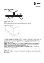
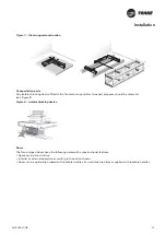
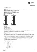
If the unit is delivered in more than one section: After connecting each section, roof position should be adjusted
on-site to compensate for the the gasket thickness between the two sections. To do that, gently unfasten the screws
fixing the roof to the unit, and slide the roof until you have the correct connection and assembly (see Figure 3).
CAUTION!:
Assembling clips must not be used to pull the sections together as this may cause the clips, the
assembling rivets or screws to break.
To properly position the unit on the base, it can be manhandled over a centrally positioned bar using a lever action.
In this event, the bar must only bear against the base frame.
The manufacturer assumes no responsibility for equipment damage or failure that results from this action.
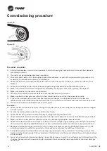
CAUTION!:
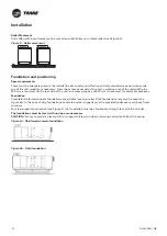
If the unit sections are mounted outdoors and are subject to atmospheric conditions, ensure the sections
are connected and well fixed to the ground. Check fixing every six months (see Figure 4).
Installation


