15
11
UNT-PRC002-GB
Sound power levels
Discharge
Measurement conditions:
Measurements taken in a room adjacent to the room containing the FWD, at the outlet of the rectangular duct (1.5 m
long) fixed to its discharge opening.
Fan
Power level in dB(A), per Hz frequency band
Overall power
Unit
speed
125
250
500
1000
2000
4000
8000
dB(A)
1
55
50
42
37
37
31
30
46
FWD 08
2
57
54
47
40
30
38
40
50
3
58
57
50
42
32
40
43
53
1
57
51
45
42
34
33
28
48
FWD 10
2
58
54
48
45
38
39
35
51
3
60
58
50
48
40
42
39
54
1
57
51
45
42
34
33
28
48
FWD 12
2
58
54
48
45
38
39
35
51
3
60
58
50
48
40
42
39
54
1
56
62
50
48
39
38
36
56
FWD 14
2
61
66
55
53
47
46
45
60
3
63
69
58
56
50
50
49
63
1
57
63
51
49
40
39
37
57
FWD 20
2
61
66
55
53
47
46
45
60
3
63
69
58
56
50
50
49
63
Intake
Measurement conditions:
Measurements taken at the horizontal air intake.
Fan
Power level in dB(A), per Hz frequency band
Overall power
Unit
speed
125
250
500
1000
2000
4000
8000
dB(A)
1
56
55
55
53
46
45
42
57
FWD 08
2
63
62
60
60
53
53
53
64
3
66
65
63
62
56
55
57
67
1
62
58
55
58
51
48
44
61
FWD 10
2
66
63
60
62
56
55
52
66
3
70
67
63
65
59
59
57
69
1
62
58
55
58
51
48
44
61
FWD 12
2
66
63
60
62
56
55
52
66
3
70
67
63
65
59
59
57
69
1
66
65
65
65
57
50
46
68
FWD 14
2
73
72
69
71
64
59
57
74
3
78
76
73
75
69
64
63
78
1
68
72
64
64
56
52
50
69
FWD 20
2
76
76
68
71
65
61
61
75
3
78
79
71
74
69
66
66
78
AH-SVX03C-GB
CAUTION!
After wiring is complete, ensure that grounding between the fan motor assembly and casing is suitable
for the electrical supply wire. If the unit is provided with an electric heater, interlock the heater contactors with a
normally closed contact to the fan contactors to avoid overheating. Switch off the fan only after leaving sufficient
time after the heater is switched off, to allow it to cool down. Electrical grounding is required between the unit and
the ductwork.
The fan-motor base is electrically insulated from the rest of the unit and the connections must be made with the
proper section copper wire. In order to warranty electrical continuity between sections, each section must be
grounded. Ground bolts are not provided. To ground the unit, use a bolt already on the unit or screw it onto the base.
The operator safety can be ensured by either a belt guard or a factory-mounted micro-switch on the fan section door.
The electrical connection of this micro-switch made by the contactor will cut off the electrical feeding to the motor
and stop the fan-motor group when the door of the fan section is opened.
Motor connection
As a safety measure against overload, short circuit, high or low voltage, a faulty connection or phase failure
impeding the cooling effect, excessively high ambient temperature, e.g. warmth from external sources, excessive
braking of the rotor, frequent switching and uncontrolled start up and stop procedures, the use of full motor
protection is necessary to protect motor windings. Use thermal protection devices to protect the motor that includes
a complete motor protection control system. Only in this manner is the manufacturer's guarantee secured.
In instances where a motor protection cut out is fitted, the correct power rating for the setting may be noted from the
product name plate.
CAUTION!
If motor is equipped with a safety thermistor or similar devices (PTC, PTO, Klixon, etc…), it is mandatory
to connect them to protect the motor.
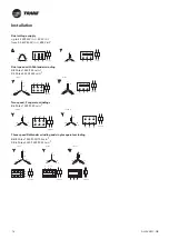
The connection must be carried out in accordance with the motor nameplate and the wiring diagrams as shown in
the inside of the motor terminal box or, generally, in accordance with the wiring diagram as shown in Table 1.
Special care should be taken in the connection of motors, especially if multi-speed motors are involved.
For fan sections equipped with double fans and motors, interlock both motors so that one motor stop command
causes the second motor to stop. Please see the Pre-start checklist section for additional information.
Following the connection of the motor, a test run should be carried out to check the motor performance data. Please
refer to the Commissioning Procedure section in this manual.
CAUTION!
In the event of motor damage resulting from faulty connection of the motor, we will not accept any
related claims.
Table 1 –
Motors with thermistors
Single speed
4 poles
1500 min-1
2 poles
3000 min-1
CAUTION!
With a star-delta starter, the motor must start with the star connections for a short period of time
(approximately 3 seconds) and then switch to the delta connections.
Installation


