CLCH-PRC03C-EN
13
Dimensions and Weights
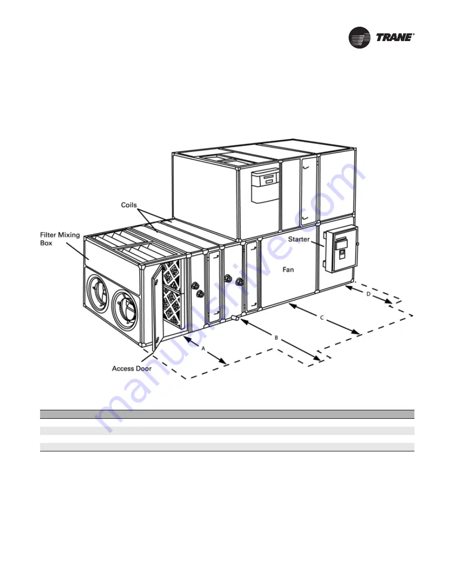
Service Clearances
Figure 1.
Service Clearance
Table 1.
Service clearances (inches)
Clearance Items
3
6
8
10
12
14
17
21
25
30
35
40
50
57
66
80
100 120
A (filter)
48
48
48
48
48
48
48
48
48
48
48
48
48
48
52
56
58
58
B (coil)
48
60
64
75
79
83
89
91
93
106
110
123
134
134
150
150
165
165
C (fan)
48
48
48
51
54
58
61
60
66
66
65
70
77
77
93
91
101
101
D (starter or VFD)
60
60
60
60
60
60
60
60
60
60
60
60
60
60
60
60
60
60
Note:
At a minimum, the above clearance dimensions are recommended on one side of the unit for regular service and maintenance. Refer to as-built
submittal for locations of items such as filter access doors, coil, piping connections, motor locations, etc. Sufficient clearance must be provided on
all sides of unit for removal of panels or module-to-module attachment brackets. Clearance for starters, VFDs, or other high-voltage devices must
be provided per NEC requirements.


