102
CVHH-SVX001G-EN
Remaining carbon capacity% =
100 - (pump-out minutes since last regen/pump-out
minutes at 100% capacity)*100
For example, an R-1233zd-equipped chiller that has
accumulated 80 minutes of purge pump-out time since
the last carbon tank regeneration would be estimated
to have 84 percent carbon tank capacity remaining:
100 – (80/500)*100 = 84%
The purge controls may initiate a carbon tank
regeneration cycle when the remaining carbon tank
capacity is calculated to be less than 80 percent.
However, the continued stable operation of the chiller
is always more important than the regeneration of the
carbon tank. Therefore, the following rules apply:
1. If the Daily Pump-out Limit is disabled, a
regeneration cycle may not be initiated, regardless
of the value of the remaining carbon capacity.
Also, if the Daily Pump-out Limit is disabled during
a regeneration cycle, the regeneration cycle must
be terminated.
2. When the remaining carbon capacity is less than
80 percent, a regeneration cycle will be initiated at
the next opportunity when the chiller is running
(after the chiller has started and no pump-out
minutes have accumulated for the previous
60 minutes).
3. If there is no opportunity to purge as indicated by
Rules 1 and 2 and the remaining carbon capacity is
less than 50 percent, a regeneration cycle will be
initiated at the best opportunity when the chiller is
shut down (and no pump-out minutes have
accumulated for the previous 60 minutes).
4. If there is no opportunity to regenerate as indicated
by Rules 1, 2, and 3 and the carbon capacity drops
below 0 percent, then a regeneration cycle is
initiated.
5. Note that, if at any time during the regeneration
cycle the chiller is running and shuts down or if the
chiller is off and starts up, then the regeneration
cycle is continued.
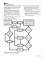
Carbon Tank Regeneration Sequence
W
WA
AR
RN
NIIN
NG
G
H
Ha
azza
arrd
do
ou
uss V
Vo
olltta
ag
ge
e!!
F
Fa
aiillu
urre
e tto
o d
diisscco
on
nn
ne
ecctt p
po
ow
we
err b
be
effo
orre
e sse
errv
viicciin
ng
g cco
ou
ulld
d
rre
essu
ulltt iin
n d
de
ea
atth
h o
orr sse
erriio
ou
uss iin
njju
urry
y..
D
Diisscco
on
nn
ne
ecctt a
allll e
elle
eccttrriicc p
po
ow
we
err,, iin
nccllu
ud
diin
ng
g rre
em
mo
otte
e
d
diisscco
on
nn
ne
eccttss b
be
effo
orre
e sse
errv
viicciin
ng
g.. F
Fo
ollllo
ow
w p
prro
op
pe
err
llo
occkko
ou
utt//tta
ag
go
ou
utt p
prro
occe
ed
du
urre
ess tto
o e
en
nssu
urre
e tth
he
e p
po
ow
we
err
cca
an
n n
no
ott b
be
e iin
na
ad
dv
ve
errtte
en
nttlly
y e
en
ne
errg
giizze
ed
d.. V
Ve
erriiffy
y tth
ha
att n
no
o
p
po
ow
we
err iiss p
prre
esse
en
ntt w
wiitth
h a
a v
vo
ollttm
me
ette
err..
X39003892001A
N
No
otte
e:: Graphic labels (shown above) are used for CE
application only.
IIm
mp
po
orrtta
an
ntt::
•
Before servicing, disconnect all power
sources and allow at least 30 minutes
for capacitors to discharge.
•
All electrical enclosures—unit or remote
—are IP2X.
If the purge controller determine that carbon tank
regeneration is desired and is allowed, the purge
controls:
1. Disable the purge refrigeration circuit and the
pump-out solenoid valve.
2. Open the regeneration solenoid valve and turn on
the carbon tank heater.
3. Monitor the carbon temperature until it reaches the
regeneration temperature value of 240°F (115.6°C),
and control within a ±10°F (5.6°C) dead band for
15 minutes (this step should take approximately
three hours).
•
If the carbon tank temperature does not increase
more than 25°F (13.9°C) in the first two hours,
the controller generates a non-latching
diagnostic, Carbon Regeneration Temperature
Too Low, and indicates a status of Carbon
Regeneration Disabled. The purpose of this
diagnostic is to identify a failed heater or
temperature sensor. It prevents automatic
regeneration from occurring, but a service
technician can initiate a manual regeneration for
Summary of Contents for CVHH CenTraVac
Page 126: ...126 CVHH SVX001G EN N No ot te es s ...


