CVHH-SVX001G-EN
25
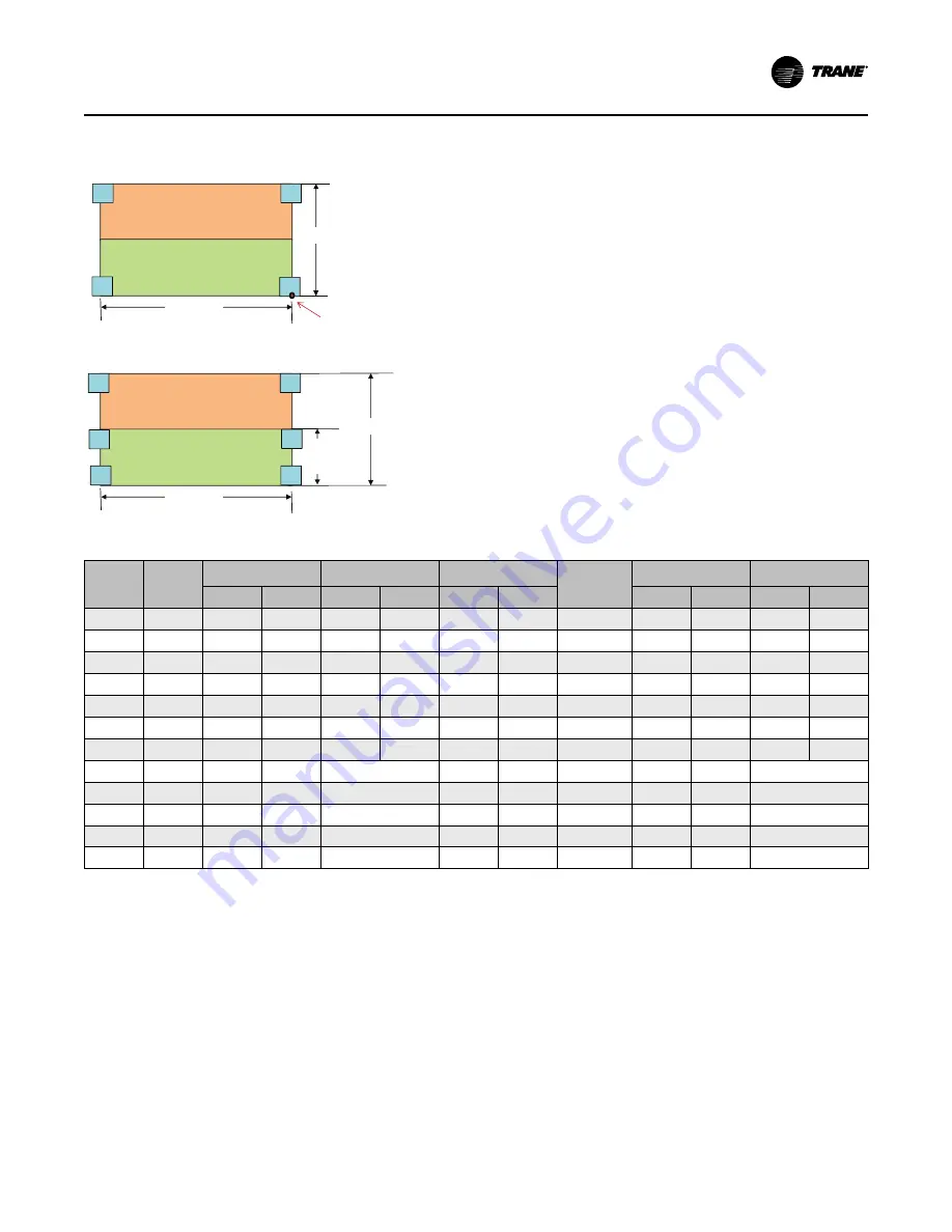
Figure 10.
Isolation spring placement
1
2
3
4
1
2
3
4
5
6
Isolator Configuration 1
Isolator Configuration 2
Width
Length
Evap
Width
Length
Width
Origin:
Right front corner of
evap right front foot
Condenser
Evaporator
Condenser
Evaporator
Table 8.
Isolation spring placement
EVSZ
CDSZ
Width
Evap Width
Length
Isolator
Config
Origin to Center
of Rear Pad
Origin to Center
of Middle Pad
in.
cm
in.
cm
in.
cm
in.
cm
in.
cm
200L
200L
112.2
285.0
67
170.2
180
457.2
2
105.7
268.5
60.5
153.7
220L
220L
119.4
303.3
74
188.0
180
457.2
2
112.9
286.8
67.5
171.5
200L
20HL
132.3
336.0
67
170.2
180
457.2
2
125.8
319.5
60.5
153.7
220L
22HL
142.5
361.0
74
188.0
180
457.2
2
136.0
345.4
67.5
171.5
160M
20HM
127.3
323.3
61
154.9
160
406.4
2
120.8
306.8
54.5
138.4
200L
220L
112.3
285.2
67
170.2
180
457.2
2
105.8
268.7
60.5
153.7
160M
200M
106.4
270.3
61
154.9
160
406.4
2
99.9
253.7
54.5
138.4
100M
100M
104.1
264.4
—
160
406.4
1
97.6
247.9
—
100L
100L
104.1
264.4
—
180
457.2
1
97.6
247.9
—
130M
130M
109.3
277.6
—
160
406.4
1
102.8
261.1
—
100M
10HM
118.2
300.2
—
160
406.4
1
111.7
283.7
—
130M
13HM
123.4
313.4
—
160
406.4
1
116.9
296.9
—
Spring isolators typically ship assembled and ready for
installation. To install and adjust the isolators properly,
follow the provided instructions.
N
No
otte
e:: Do NOT adjust the isolators until the chiller is
piped and charged with refrigerant and water.
IIm
mp
po
orrtta
an
ntt:: Do NOT block any serviceable components
such as the lubrication system with field-
installed devices such as spring isolators.
1. Position the spring isolators under the chiller as
shown in the preceding figure. Ensure that each
isolator is centered in relation to the tube sheet.
N
No
otte
e:: Spring isolators shipped with the chiller may
not be identical. Compare the data provided
in the unit submittal package to determine
proper isolator placement.
2. Set the isolators on the sub-base; shim as
necessary to provide a flat, level surface at the
same elevation for the end supports.
IIm
mp
po
orrtta
an
ntt:: Support the full underside of the
isolator base plate; do NOT straddle
gaps or small shims.
3. If required, screw the isolators to the floor through
the slots provided, or cement the pads.
N
No
otte
e:: Fastening the isolators to the floor is not
necessary unless specified.
Summary of Contents for CVHH CenTraVac
Page 126: ...126 CVHH SVX001G EN N No ot te es s ...


