CVHH-SVX001G-EN
73
Table 24. Unit control panel wiring 120 Vac (continued)
(b)
If the Condenser Water Flow Proving Input is a factory-installed ifm efector
®
flow-sensing device, the secondary (optional) field device for proof of flow
connects from 1X1-6 to 1K27-4 (binary input; normally open, closure with flow). Remove factory jumper when used.
(c)
Standard low-voltage circuits (less than 30 Vac) must be separated from 120 Vac or higher wiring.
Water Pump Interlock Circuits
and Flow Switch Input
W
WA
AR
RN
NIIN
NG
G
H
Ha
azza
arrd
do
ou
uss V
Vo
olltta
ag
ge
e!!
F
Fa
aiillu
urre
e tto
o d
diisscco
on
nn
ne
ecctt p
po
ow
we
err b
be
effo
orre
e sse
errv
viicciin
ng
g cco
ou
ulld
d
rre
essu
ulltt iin
n d
de
ea
atth
h o
orr sse
erriio
ou
uss iin
njju
urry
y..
D
Diisscco
on
nn
ne
ecctt a
allll e
elle
eccttrriicc p
po
ow
we
err,, iin
nccllu
ud
diin
ng
g rre
em
mo
otte
e
d
diisscco
on
nn
ne
eccttss b
be
effo
orre
e sse
errv
viicciin
ng
g.. F
Fo
ollllo
ow
w p
prro
op
pe
err
llo
occkko
ou
utt//tta
ag
go
ou
utt p
prro
occe
ed
du
urre
ess tto
o e
en
nssu
urre
e tth
he
e p
po
ow
we
err
cca
an
n n
no
ott b
be
e iin
na
ad
dv
ve
errtte
en
nttlly
y e
en
ne
errg
giizze
ed
d.. V
Ve
erriiffy
y tth
ha
att n
no
o
p
po
ow
we
err iiss p
prre
esse
en
ntt w
wiitth
h a
a v
vo
ollttm
me
ette
err..
X39003892001A
N
No
otte
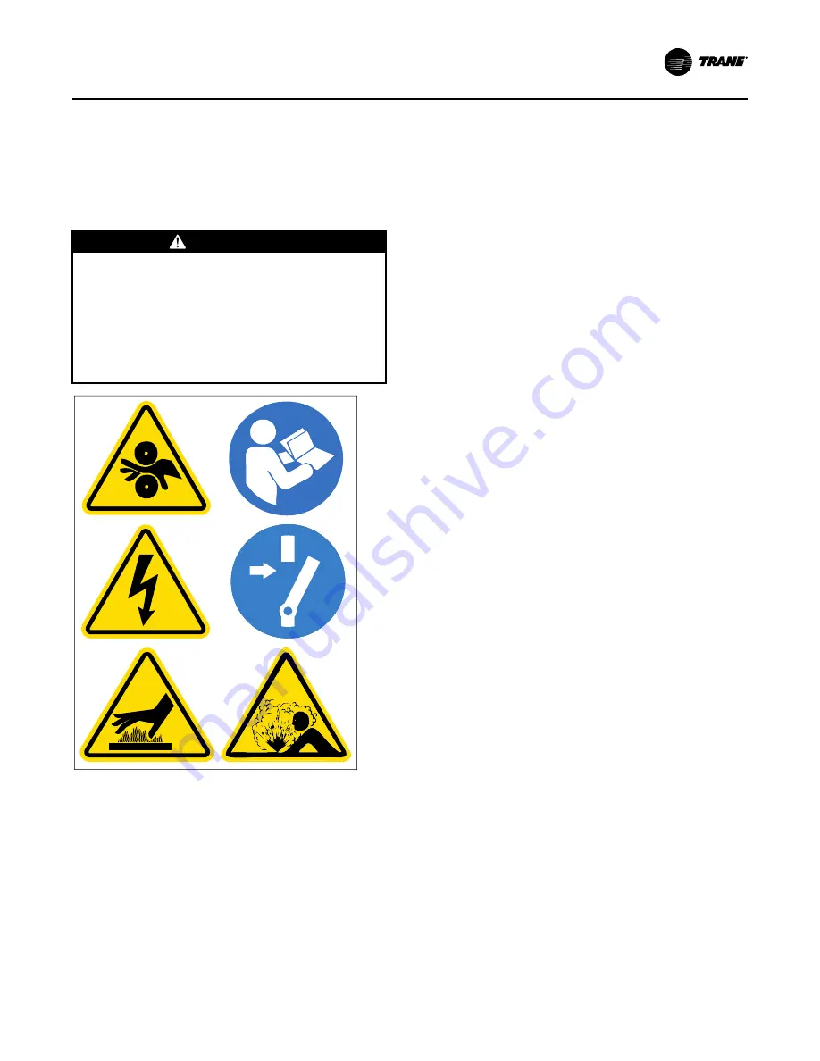
e:: Graphic labels (shown above) are used for CE
application only.
IIm
mp
po
orrtta
an
ntt::
•
Before servicing, disconnect all power
sources and allow at least 30 minutes
for capacitors to discharge.
•
All electrical enclosures—unit or remote
—are IP2X.
N
No
otte
e:: The circuits for the chilled water proof of flow
and the condenser water proof of flow do NOT
require external power. Refer to the wiring
diagrams that shipped with the chiller.
Chilled Water Pump
1. Wire the evaporator water pump contactor (5K42)
to a separate 120 volt single-phase power supply
with 14 AWG, 600V copper wire. For AWG/MCM
equivalents in mm
2
, refer to the table in
.
2. Connect circuit to 1K15-J2-6.
3. Use 1K15-J2-4 120 Vac output to allow the control
panel to control the evaporator water pump, or wire
the 5K1 contactor to operate remotely and
independently of the control panel.
Chilled Water Proof of Flow
When this circuit is installed properly and the
evaporator pump is running and providing the required
minimum flow, this circuit will prove the evaporator
water flow for the chiller controls. Proof of evaporator
water flow is required before the start sequence will be
allowed to proceed and a loss of evaporator water flow
during chiller operation will result in a chiller shut-
down.
Refer to as-built schematics on the inside of the control
panel for field wiring. This is a dry binary input;
normally-open, closure for flow. Apply no external
power.
1. With factory-installed ifm efector
®
flow-sensing
devices, a field-provided secondary flow-sensing
device is recommended with applications having
38°F (3.3°C) and below leaving evaporator water
temperatures. When a secondary flow-sensing
device is used, remove the factory jumper and
install its contacts between 1X1-5 to 1K26-4; this
places the secondary flow sensing device in series
with the ifm efector
®
flow-sensing device.
2. For field-provided primary proof of flow devices,
connect the primary proof of flow device between
terminals 1X1-5 to 1K16-J3-2. A secondary field
device is recommended with applications having
38°F (3.3°C) and below leaving evaporator water
temperatures, and must be field-wired in series
with the primary proof of flow device.
Condenser Water Pump
1. Wire the condenser water pump contactor (5K43) to
a separate 120-volt, single-phase power supply with
14 AWG, 600-volt copper wire. For AWG/MCM
equivalents in mm
2
, refer to the table in
.
2. Connect circuit to control panel terminals 1K15-J2-
3.
3. Use 1K15-J2-1 120 Vac output to allow the control
Summary of Contents for CVHH CenTraVac
Page 126: ...126 CVHH SVX001G EN N No ot te es s ...


