Power Supply Wiring
CVHH-SVX001A-EN
59
Connect T1 to T6, T2 to T4, and T3 to T5.
N ot e: Bus bars are not needed in m edium -voltage or
high-voltage applications since only 3 term inals
are used in the m otor and starter.
Starter to Control Panel Wiring
The unit subm ittal includes the field w iring connection
diagram and the starter-to-control-panel connection
diagram (show ing the electrical connections required
betw een the rem ote-m ounted starter and the control
panel).
N ot e: Install separate conduit into the low voltage
(30 volts) section of the control panel.
When sizing and installing the electrical conductors for
these circuits, follow the guidelines listed. Use 14 AWG for
120V control circuits unless otherw ise specified. For AWG/
M CM equivalents in m m
2
, refer to
Table 12, p. 47
.
Im port ant :
M aintain at least 16 cm (6 in.) betw een low-
voltage (<30V) and high voltage circuits.
Failure to do so could result in electrical
noise that m ay distort the signals carried by
the low voltage w iring, including the IPC
w iring.
To w ire the starter to the control panel, follow the
guidelines below :
•
If the starter enclosure m ust be cut to provide electrical
access, exercise care to prevent debris from falling
inside the enclosure. Do not cut AFD enclosure.
•
Use only shielded, tw isted-pair w iring for the
Interprocessor Com m unication (IPC) circuit betw een
the starter and the control panel on rem ote m ounted
starters.
N ot e: Recom m ended w ire is Beldon Type 8760,
18 AWG for runs up to 304.8 m (1000 ft). For
AWG/M CM equivalents in m m
2
, refer to
Table 12, p. 47
. The polarity of the IPC w iring is
critical for proper operation.
•
Separate low-voltage (less than 30V; refer to
Table 13,
p. 48
) w iring from the 115V w iring by running each in
its ow n conduit.
•
When routing the IPC circuit out of the starter
enclosure, ensure that it is at least 16 cm (6 in.) from all
w ires carrying a higher voltage.
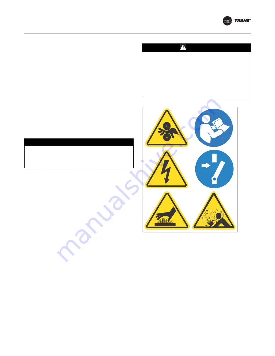
N ot e: Graphic labels (show n above) are used for CE
application only.
Im port ant :
•
Before servicing, disconnect all pow er sources and
allow at least 30 m inutes for capacitors to discharge.
•
All electrical enclosures—unit or rem ote—are IP2X.
•
The IPC w iring shield should be grounded on one end
only at control panel end.The other end should be un-
term inated and taped back on the cable sheath to
prevent any contact betw een shield and ground.
•
Oil Pum p Interlock: All starters m ust provide an
interlock (norm ally open) contact w ith the chiller oil
pum p connected to the control panel at term inals
1X1-10 and 1X1-21 (14 AWG; for AWG/M CM
equivalents in m m
2
, refer to
Table 12, p. 47
.) The
purpose of this interlock is to m aintain the oil pum p
signal in the event that a starter failure, such as w elded
contacts, keeps the chiller m otor running after the
controller interrupts the run signal.
NOTICE:
Component Damage!
Remove all debris from inside the starter panel. Failure
to do so could result in an electrical short and could
cause serious starter component damage.
WARNING
Proper Field Wiring and Grounding
Required!
Failure to follow code could result in death or serious
injury. All field w iring M UST be performed by qualified
personnel. Improperly installed and grounded field
w iring poses FIRE and ELECTROCUTION hazards. To
avoid these hazards, you M UST follow requirements for
field w iring installation and grounding as described in
NEC and your local/ state/ national electrical codes.
X39003892001A
Summary of Contents for CVHH
Page 110: ......


