Start-up and Shut-dow n
78
CVHH-SVX001A-EN
If the STOP key is pressed on the operator interface, the
chiller w ill follow the sam e stop sequence as above except
the chilled water pum p relay w ill also open and stop the
chilled water pum p after the chilled water pum p delay
tim er has tim ed out after com pressor shut dow n (see
Figure 45
).
If the “ Im m ediate Stop” is initiated, a panic stop occurs
w hich follow s the sam e stop sequence as pressing the
STOP key once except the inlet guide vanes are not
sequence closed and the com pressor m otor is
im m ediately turned off.
Power Up Diagram
Figure 42, p. 76
illustrates Tracer AdaptiView during a
pow er up of the m ain processor. This process takes from
30 to 50 seconds depending on the num ber of installed
Options. On all pow er ups, the software m odel always w ill
transition through the Stopped software state
independent of the last m ode. If the last m ode before
pow er dow n was Auto, the transition from Stopped to
Starting occurs, but it is not apparent to the user.
Ice M achine Control
The control panel provides a service level Enable or
Disable m enu entry for the Ice Building feature w hen the
Ice Building option is installed. Ice Building can be entered
from Front Panel, or if hardware is specified the control
panel w ill accept either an isolated contact closure 1K9
Term inals J2-1 and J2-2 (Ground)) or a rem ote
com m unicated input (BAS) to initiate the ice building
m ode w here the unit runs fully loaded at all tim es. Ice
building w ill be term inated either by opening the contact
or based on entering evaporator fluid tem perature. The
control panel w ill not perm it the Ice Building m ode to be
entered again until the unit is sw itched to the non-ice
building m ode and back into the ice building m ode. It is not
acceptable to reset the chilled water setpoint low to
achieve a fully loaded com pressor. When entering ice
building, the com pressor w ill be loaded at its m axim um
rate and w hen leaving ice building the com pressor w ill be
unloaded at its m axim um rate. While loading and
unloading the com pressor, all surge detection w ill be
ignored. While in the ice building m ode, current lim it
setpoints less than the m axim um w ill be ignored. Ice
Building can be term inated by one of the follow ing m eans:
•
Front panel disable.
•
Opening the external Ice. Contacts/ Rem ote
com m unicated input (BAS).
•
Satisfying an evaporator entering fluid tem perature
setpoint (default is -2.8°C [27°F]).
•
Surging for 7 m inutes at full open IGV.
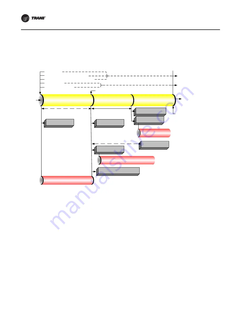
Figure 45.
Sequence of operation: normal shut-dow n to stopped and run inhibit
Local Stop
Normal Latching Diagnostic
Normal Non-Latching Diagnostic
Tracer Stop
External Auto-Stop
IGV Closed
Preparing Shutdown
Shutting Down
Shutting Down
Running
Stopped
Run Inhibit
Stopped
or
Run Inhibit
Evap Pump
Off Delay
and Postlube
Complete
Close IGV (0–50 sec)
Postlube 3 min
Evap Pump Off Delay Time
(0–30 min)
Command IGV Closed
Enforce All Running Mode Diagnostics
De-Energize Condenser
Water Pump Relay
De-Energize
Compressor
Confirm No Compressor Currents
Within 8 sec
Hold position of Oil Vent Line Valve
Open Oil Vent Line Valve
De-Energize Oil Pump
Confirm No Oil Pressure*
5 min after oil pump
is de-energized
De-Energize Evaporator
Water Pump Relay
*Note: No oil pressure is less than 20.7 kPad (3 psid)
Summary of Contents for CVHH
Page 110: ......


