background image

10 


32-5035-13

User’s Information

3.  IGNITER – This unit has a special hot surface di- 
 

rect  ignition  device  that  automatically  lights  the  


burners.  Please  note  that  it  is  very  fragile  and  


should be handled with care.

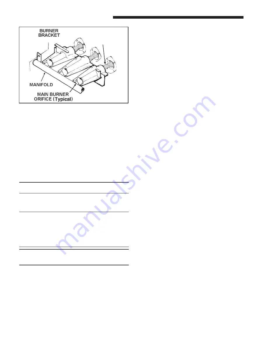
4.  BURNER  –  Gas  burners  do  not  normally  require  
 

scheduled servicing, however, accumulation of for- 


eign  material  may  cause  a  yellowing  flame  or  de- 


layed ignition. Either condition indicates  that a ser- 


vice  call  is  required.  For  best  operation,  burners 


must  be  cleaned  annually  using  brushes  and  


vacuum cleaner.

Turn off gas and electric power supply.  To clean burn-
ers,  remove  top  burner  bracket  and  lift  burner  from 
orifice. 

NOTE: Be careful NOT to break igniter when removing 

burners.

 
Clean burners with brush and/ or vacuum cleaner. Re-
assemble parts by reversal of the above procedure.

NOTE: On LP (propane) units, some light yellow tipping 

of  the  outer  mantle  is  normal.  Inner  mantle  should  be 

bright blue. Natural gas units should not have any yel-

low  tipped  flames. This  condition  indicates  that  a  ser-

vice call is required. For best operation, burners must 

be cleaned annually using brushes and vacuum clean-

er.

NOTE: On LP (propane) units, due to variations in BTU 

content  and  altitude,  servicing  may  be  required  at 

shorter intervals.

5.   HEAT  EXCHANGER / FLUE  PIPE  –  These  items 

must be inspected for signs of corrosion, and/ or de-
terioration at the beginning of each heating season 
by a qualified service technician and cleaned annu-
ally for best operation. 

6.   CIRCUIT  PROTECTION  –  If  blower  or  gas  valve 

fail to operate, the cause could be the circuit break-
er  or  a  loose  or  blown  fuse.  Replace  fuse  or  reset 
circuit breaker.

FLAME

7.   OPERATION – Your warm air furnace should not 

be  operated  in  a  corrosive  atmosphere.  Paint  sol-
vents,  cleaning  chemicals,  spray  propellants,  and 
bleaches  should  not  be  used  in  the  vicinity  of  the 
furnace during normal operation.

8.   CONDENSATE  DRAINS  –  If  you  have  a  cooling 

coil installed with your furnace, condensate drains 
should  be  checked  and  cleaned  periodically  to  as-
sure  that  condensate  can  drain  freely  from  coil 
to  drain.  If  condensate  cannot  drain  freely  water 
damage could occur. Furnace drain should also be 
checked & cleaned at the start of each heating sea-
son.

9.   AIR  CIRCULATION  –  To  ensure  increased  com-

fort, the blower on this unit may be operated con-
tinuously  for  both  heating  and  cooling.  This  will 
result  in  constantly  filtered  air  and  aid  in  main-
taining  more  even  temperatures  by  avoiding  tem-
perature  stratification  throughout  the  conditioned 
area.    To  accomplish  constant  air  circulation,  set 
your comfort control fan selector to “ON”. Continu-
ous fan mode during COOLING operation may not 
be appropriate in humid climates. If the indoor air 
exceeds 60% relative humidity or simply feels un-
comfortably humid, it is recommended that the fan 
only be used in the "AUTO" mode.”

Summary of Contents for DD-ACV

Page 1: ...switch do not use any phone in your building Immediately call your gas supplier from a neighbor s phone Follow the gas supplier s instructions If you cannot reach your gas supplier call the fire depar...

Page 2: ...iate NIOSH approved respirator in these situations FIRST AID MEASURES Eye Contact Flush eyes with water to remove dust If symptoms persist seek medical attention Skin Contact Wash affected areas gentl...

Page 3: ...Also air openings provided to the area in which the fur nace is installed and the space around the furnace shall not be blocked or obstructed Keep this in mind should you choose to remodel the area w...

Page 4: ...Start the Furnace Your furnace will have a switch to turn the gas ON or OFF 5 Turn the external main gas shutoff valve and the toggle switch located on the main gas valve inside the unit to the ON pos...

Page 5: ...ny questions UPFLOW FURNACE Manual Main Gas Shut off Valve May Be Located on the Left or Right Side DOWNFLOW FURNACE Manual Main Gas Shutoff Valve May Be Located on the Right or Left Side AUTOMATIC GA...

Page 6: ...er a BOTTOM or SIDE left or right return air inlet The filter may be secured with filter retaining brackets as shown or a filter rack To clean or replace filters remove blower access door slide the fi...

Page 7: ...n both top and bot tom filter brackets Replace filter access door REQUIRED FILTERS BOTTOM CABINET WIDTH FILTER QUANTITY SIZE 17 1 2 1 17 X 25 X 1 21 1 20 X 25 X 1 24 1 2 1 24 X 25 X 1 REQUIRED FILTERS...

Page 8: ...r syn thetic solvents may damage the finish DOWNFLOW Vertical FILTER TABLE REQUIRED FILTERS DOWNFLOW CABINET WIDTH FILTER QUANTITY SIZE 17 1 2 2 14 X 20 X 1 21 2 16 X 20 X 1 24 1 2 2 16 X 20 X 1 DOWNF...

Page 9: ...so as to provide a seal between the support and the base e There are no obvious signs of deterioration of the furnace f The burner flames are in good adjustment without erratic flames See illustation...

Page 10: ...corrosion and or de terioration at the beginning of each heating season by a qualified service technician and cleaned annu ally for best operation 6 CIRCUIT PROTECTION If blower or gas valve fail to...

Page 11: ...the gas furnace is 1 installed by a licensed or qualified HVAC technician 2 applied and installed in accordance with the manufacturer s recommendations in its Installer s Guide and 3 in compliance wit...

Page 12: ...d then liability shall be limited solely to the purchase price of the equipment under warranty shown to be defective This limited warranty does not apply if the gas furnace was purchased direct i e fr...

Page 13: ..._________________________________________________________ Indoor Coil Serial Number______________________________________________________________________________ Indoor Coil Model Number______________...

Page 14: ...hange design and specifications without notice Trane 6200 Troup Highway Tyler TX 75707 For more information contact your local dealer distributor File name 32 5035 13 Supersedes 32 5035 12 Date 10 09...

Reviews: